High Fidelity
What does music sound like?
I think everyone will agree that there is something special about listening to a live music performance, whether this be in a recording studio, a Jazz club, or a live concert. The sound of instruments being played mixes with the ambience of location to provide that unmistakable sensation that anything is possible. In High Fidelity we attempt to keep as much of this authentic sensation alive as possible, but, regardless of how much money we spend, more often than not, the result we achieve in our homes is much less. However, this does not necessarily mean that our system as such is at fault or that we cannot afford what it takes to preserve the musicality of the original event.
In a typical household environment many factors will have a marked influence on the quality of sound that have little or nothing to do with the equipment itself, but rather with how it is connected, where it is placed, and with the characteristics of the room. The following steps are intended to provide an overview of the factors involved in maintaining sonic integrity, from the source of the system’s energy all the way to energizing the room.
From Power to Speaker
1. The Power Source

Since the basis of any system is electric power, this is a good place to start setting up our system. Depending on the time and effort we are willing to invest, we might start by having a slow-blowing fuse installed and running a dedicated power mains from the central fuse cabinet to our system.
The distortion to be found on a power grid can be measured and shown. It comes from many sources, such as trailing edge dimmers and transformers found on LED lights, from local industry, from refrigerator motors, from switches, WiFi networks etc.
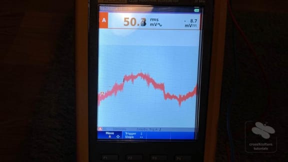
The picture shows measurements made in our apartment. The spikes show the level of distortion and interference as described above. Since we are renting, I did not have the luxury of running a dedicated cable, but I did locate the socket with the least distortion, and I am running a 2.5mm solid core house installation wire from there. This type of wire is not meant to be moved around, I therefore installed a cable duct to keep it in position and protect it from wear.
2. Power distribution

Once we have located the cleanest possible power source for our HiFi system, the next challenge will be the distribution of this power to an array of audio devices. Separate units do not necessarily 'sound better' than their high quality combined equivalents, yet, separates have the advantage of allowing for some 'later stage adjustments' when calibrating a system to the room, the preferred style of music, and individual taste without the use of attenuators.
The units may be: a CD player and turntable, a DAC, an audio streamer, a pre-amp, a power amp, and possibly more. A dedicated audio power strip will be designed to minimise differences in electric potentials between the devices, thus leading to a more even flow of current. Such power strips come in many shapes and price ranges.
For my own low budget setup I bought a used Audioplan PowerStar 'cookie jar' distributor and had 3m of shielded 2.5mm Lapp Ölflex power cord attached to this. This is nicely fitted with a gold plated heavy duty power plug.
From my own experience, all cables, even power cables, will need some time to run in before showing their full sonic potential. I have never connected a new cable that did not drastically change its effect on the music within the first three days of playing.
Next to proper phasing, the precise position of a plug in relation to the other components on the power strip may make a big sonic difference. The traditional order is: amp, pre-amp, turntable, and the rest, with digital as far away as possible. However, since there is no definite rule, we have no other choice but to test different combinations ourselves.
3. Power cords

Coming from a dedicated power strip or directly from a wall socket, our clean power will need to be forwarded to each of the HiFi units, at a typical distance of less than 1.5m. Although this distance is relatively small when compared to the house installation, the sonic difference between a standard supply cord and one that has been engineered for audio usage is quite enormous.
Especially to amps and preamps, the power cord is of such importance to the overall sound integrity that we are well advised to invest at least 10% of the unit price on the power plugs and cord. Typical HiFi cords will be designed on the basis of 2.5mm diameter wires. However, diameter is not everything. There are cords of smaller diameter with excellent sonic characteristics.
On my own vintage units not all cords are removable. I upgraded the cords on the amps (during recap) as well as on the high-voltage transformers of the electrostatic speakers, and I made sure that the general power strip is also equipped with an excellent cord. - Especially on the amps, the new cords have greatly contributed to the system's improved musicality.
4. Power filtering

The better our system is designed, the more it will reveal flaws in the electric current. HF interference is such a flaw and can be found to various degrees in all households environments. Interference comes from modern lighting, communication equipment, and from many other sources.
HF interference will destroy the sonic integrity of our system right from the source, e.g. by saturating the iron core of the power transformers. The acoustic effect will be a subtle leaning of the system towards harshness, technicality, and a tin-like ringing in the highs leading to early listening fatigue.

While there are many pricy solutions to combat the issue, there are two relatively affordable interventions: ferrite clamps and shunt filters (also called power conditioner or noise trap). I have achieved excellent results by placing one ferrite clamp on each power cord and one clamp on the power strip lead. For maximum effect, all ferrite clamps are mounted in a position just before the cable enters the housing. In addition, a power conditioner is plugged into the power strip.
5. Phase alignment

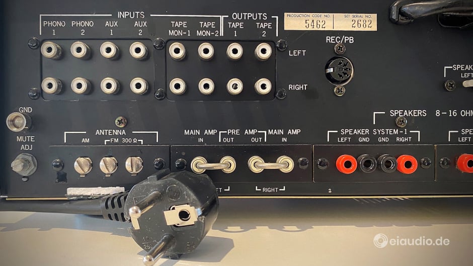
In HiFi forums it is often suggested that the polarity of a 240V plug should not matter, because the polarity is oscillating at 50Hz. However, this is not the whole truth, as only the phase oscillates while the other remains neutral. In many countries, such as the US and Britain, an inversion of the poles is prevented wherever necessary through the use of directional plugs, either through a ground prong (UK) or through one pole being larger (US). The question of whether polarity matters is therefore essentially a German one, and as such, it will never go away.
There are many ways in which to determine the correct polarity of a unit’s plug. Oehlbach suggests we use their ‘Phaser’, others favour extensive measurements with the unit being turned on and off. Regardless of the method employed, the first step will be to use a phase tester, usually a screwdriver, and to check and mark the phase on the outlet socket. When using a power strip for distribution, the phase should be marked here as well, this can be done with a white or red marker or with adhesive dots, etc.
Although I have used the Oehlbach Phaser at times, I have found the most effective method to be trial and error, using my own ears. To do so, I took an empty power strip and plugged in the minimum units I need to play music, e.g. turntable, pre-amp, amp. If your phono preamp is not located inside your turntable but in your pre-amp, the polarity of the turntable does not matter, because the audio signal path is passive. This way I only had two plugs to phase: pre-amp and amp. This limits the number of combinations.
What to listen for: When phase alignment is done poorly, the music sticks to the speakers and the phantom center (the middle position resulting from mono signals in the recording, usually the voice) will be off. When phase alignment is done correctly, the music will extend into the room, with the phantom center being as discernible as a third speaker. Do the same for each new unit you bring in, until you reach this effect. This is called phasing your system and is an interesting stage of the setup that can take some time getting used to. Once you have it right, there is no going back.
When phasing a single unit, such as a receiver, with no other units attached during listening, the effect of phasing might be less pronounced. Phasing mostly has to do with differences in electric potential between devices.
6. Pre-amplification

A pre-amplifier can well be considered the heart of our system. Since many pre-amps will feature a built-in phono stage, for MM, MC, or both, there is some amplification involved, however, the term describes more its position before the amplifier than its calling. Pre-amps generally serve as a hub to rout music signals from multiple sources to a single power amplifier. All preamps add a sonic signature, and, because of their central position, this signature will make or break a good system.
It therefore makes sense to choose our preamp well, and there are some pointers to look out for: 1. Signal integrity may be corrupted when running though potentiometers, hence, audiophile units will rarely feature bass, treble, and other attenuators. 2. Power supplies may inject interference into the signal. Many units therefore place the power supply in a separate housing. 3. Thin conductor tracks on the circuit board may cost speed and dynamics. 4. 2D circuit board layouts may pick up interference. High End units will often have a greater degree of direct wiring.
For my own system I chose a pre-amp from a lesser-known US manufacturer who have been constructing their DB Systems DB1 with the power supply DB2 from the 1970s until today with only minor changes. The unit is built under consideration of the four pointers mentioned above and produces a remarkably natural and inviting midrange with overall extremely low distortion. It can feed two amplifiers, a very convenient feature that I have at times made use of, e.g. for bi-amping hybrid speakers.
7. Interconnects
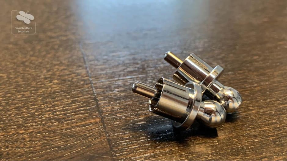
Audio signals are usually transmitted between the units by means of wires. The plugs may range from 5-pin DIN via RCA and jack-plug to XLR balanced studio standard. For home and even High End audio designs, the most common type of plug is still the RCA/cinch coupling. This type of connection has some practical advantages, e.g. no converters needed, but it also features some inherent design flaws for optimal signal transduction. Optical connection can be made via Toslink (light pulse). Although widely available, this is not commonly used by audiophiles, as the music often becomes dull, and good signal converters are rare.
As a result of all this, RCAs interconnects have long since become significant components in their own right, because, depending on the materials used in the design of cables and plugs, the sonic character of the system will be influenced by them. From detailed to confined, from dynamic to dull, our system’s musical signature will be shaped by its compatibility with the interconnects used between source and pre-amp and between pre-amp and power amplifier.
In my own tests I have found that no two interconnects create the same sonic effect and that the preference of one interconnect’s sonic characteristics over another greatly depends on the electronic environment that it is used in. This means: an interconnect that has been found to be beneficial for phono to preamp connections may well perform poorly in all other positions in our system. The phono to preamp connection is a very special one in which much attention needs to be placed on shielding to avoid humming and other interference.
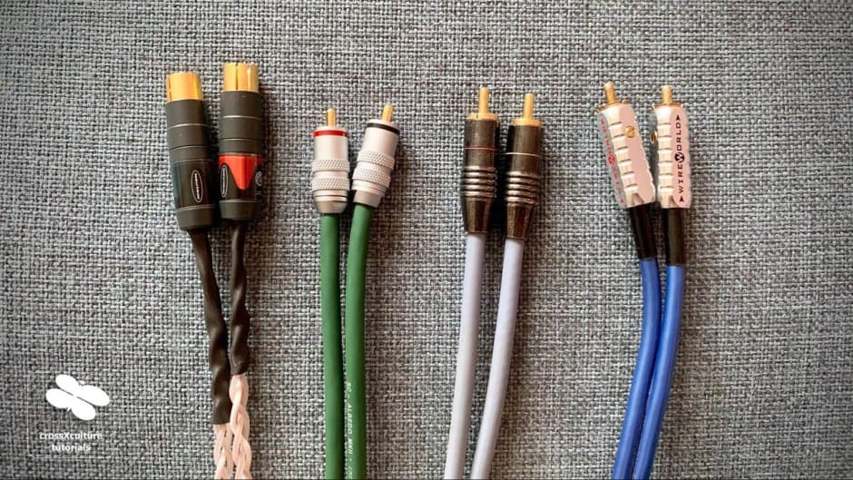
Looking at our own system, it turns out that every position is a special one. A CD player for instance may benefit from a braided wire (e.g. Western Electric, Kimber, etc.) instead of a solid shield, whereas a 5-pin to cinch (e.g. Sommer Cable) is not misplaced on an FM radio tuner. I have learned that the best way of finding the most suitable interconnect for a position is through trial and error. All interconnects shown in the picture have one thing in common: they do not fit my system in its current stage and have been replaced.
The interconnects from left to right are: 1. Neutrik NF2 (on Kimber Tonik); 2. Sommer Albedo; 3. Fadel Art IC4; 4. Wireworld Composilex 2. - Of these, only the Kimber would be considered more than Mid-Fi.
Plugs and wires individually, and especially in their combination, show different properties in terms of their resistance, capacitance, and inductance. Of the three properties, resistance is deemed to be the most significant, yet the precise combination of all three properties, over the full span of frequencies from at least 10-30.000 Hz, in the end creates the unique sonic signature of an interconnect.
In September 2019, Rainer Langlitz and I tested the resistance, capacitance, and inductance of four interconnects of different manufacturers at just one frequency (1,000 Hz) and found each one to be different from the others. Measuring the full band of frequencies would most likely have revealed each interconnect’s unique signature that sets it apart from the rest. At the time we did not have the equipment to conduct a more thorough investigation.
Quality interconnects will usually show an indication of the direction in which they should be connected. This is usually the direction in which the steel was rolled and the wire was produced. We can confirm the importance of the direction by inverting only one channel. If we have set up our system according to steps 1-7, the phantom center should be off during the inversion.

8. Power Amplification

Our pre-amplifier passes the signal it receives from the music source through to the ‘power amplifier’. If this process is combined into a single unit, this is simply called ‘amplifier’. If a tuner is added in the same housing, the unit becomes a ‘receiver’. While these combined units are often cheaper and more convenient, they also limit the options in customising our system, e.g. when changing to new speakers. - Without doubt, there are great units to be found in either discipline.
A power amplifier takes the relatively weak electrical current coming from the pre-amp and uses it to operate a regulator that controls a high current coming from the power grid. The regulator can be in the form of a transistor or a tube, or in that of a digital switch. Both transistors and tubes radiate lots of heat during operation. Tubes mostly because of their internal heating, and transistors because of their relatively slow adjusting of a high energy source. Classic transistors are round and shiny looking, similar to tubes.
An amplifier needs a strong, low radiation transformer (often toroidal or encapsulated) that delivers both the operating and the amplification current, and lots of excess energy that is stored in the large capacitors (similar to ultrafast batteries) to provide music burst power that the power grid could not otherwise provide fast enough. It also needs one operating board and at least one transistor (or similar) per channel, usually mounted on large heat sinks for cooling.
From the combination of these parts results the amplifier’s power rating. This is usually provided in two numbers: watts & ohms. The watts is the ability to provide power into a load resistance that is rated in ohms. Theoretically, when you lower the load resistance on the side of the speaker, the ability to deliver watts on the side of the amplifier increases. There is a limit to this, however, because reduced load also means more back current to the amplifier which at some point either becomes unstable or overheats and dies, perhaps taking the speakers with it.
When I first looked at the subject of power amplifiers for my system, I was surprised that some of the most highly esteemed amp designs displayed great simplicity in terms of both: components and layout. Having had the privilege to sonically compare some older with more modern designs, I am currently very pleased with the well balanced sound of the 1989 B&K ST140 amplifier that I purchased from a member of the local audiophile community. The amp's ability to deliver into a 2 ohms load was among my considerations.
9. Speaker Cables

We use speaker cables to connect the output stage of our receiver, amplifier, or power amp to our set of loudspeakers. While this sounds to be an easy enough task to perform, there are some considerations to be made to assure the best type of connection within our budget. As with all wire connections, there are the following specifications to be considered: resistance, capacitance, and inductance. Of these three properties, resistance is found to be the most significant, yet the precise combination of all three properties over the full span of frequencies will create the unique sonic signature of a speaker cable.
To assure for low resistance, speaker cables should be as short as possible and of equal lengths. Ultimately, this means we will need to place our system between the speakers, with the speakers themselves placed as close together as possible, and as wide apart as acoustically necessary, considering the room and listening position.
Since corrosion is the enemy of any connection, bare wire connections are not common among audiophile listeners. Instead of bare wire, two types of terminations are commonly used: banana plugs or spades. Mostly, the termination is soldered onto the wires, using lead or silver as base material. Screw-on terminations often displace the wire material and, with time, may lead to a poor connection. Low mass terminations, such as hollow bananas or thin spades, usually offer superior musical imaging with increased fine dynamics when compared to their higher mass gold plated alternatives found in many High End shops.
Cable designs often take into consideration the effects of interference on wires and the disparate characteristics of different strengths of wires. Kimber Cable, for example, braid their speaker wires and use different thicknesses of strands within a single cable, others may twist or externally shield their wires. Personally, I have found twisted tinned wires with beryllium hollow banana terminations to be the most musical in my systems. On the downside, tinned wires have some of the longest run-in times imaginable, with their full sonic potential taking 200+ hours of usage to unfold. Especially in the first few days, I did not find it easy to stay in the same room with them, given their at first poor sound balance. Just to compare: The run-in time for OFC copper cables is estimated at around 80 hours.
10. Speaker terminals

Most modern HiFi (mid-market to High End) speakers feature terminals equipped for the connection of two separate sets of speaker cables. This allows separate connections to be made to the tweeter (highs) and woofer (lows) drivers of each speaker. Such terminals usually come with a bridge between them to enable connections with a single cable. When the speaker terminals are driven with two separate cables, the bridge must first be taken out, and the configuration is called bi-wiring. When two amplifiers are used, e.g. one amp driving the tweeter and the other the woofer, this is called bi-amping.
Bi-amping is for instance used when a low power tube amp is to drive the high to mid section, with a beefy solid state power amp driving the bass section. However, bi-amping presents the most difficult issues to solve in trying to maintain coherence and will prove to be inferior to a conventional setup, unless we really know how to professionally phase align and fine tune such systems. The more likely option is bi-wiring or using a single cable with a bridge.
Of the three options mentioned above, I have had the most success bi-wiring with a single point of contact on the side of the amplifier. To do so, I had to design cables with two banana plugs on the side of the amp and four plugs on the side of the speaker. Of course, such cables can be bought preconfigured, but it is obviously not as much fun.
The single point of contact on the side of the amplifier makes for excellent sonic cohesion. Bi-wiring on the side of the speaker, however, carries each driver’s back-current straight to the amp terminal, without affecting the other drivers. Ideally, the wires split apart directly from the banana plug connected to the amp, with the two cables running in parallel over the distance to the speaker. This also elegantly increases the diameter without sacrificing the responsiveness of a lower diameter wire.
11. Turntables

I must confess that I am still a relative ‘newbie’ to the subject of turntables. Like most turntable owners around in the 80s, I was excited about the emergence of the new, super silent, digital technology that came in the shape of a shiny and more compact disc. And, honestly, at the affordable price range of an adolescent, the CD performed much better. I consequently sold my record player in the early 90s, never to look back until ... summer 2018, when we found a 1972 Philips 212 deck in our grandpa’s basement.
Lots of time reading and experimenting has passed since then. The Philips needed a new belt, bracket, and cartridge. We lubricated the moving parts, upgraded the internal wiring, and changed the output terminal from 5-pin DIN to RCA/cinch sockets. We checked the platter speed, corrected the azimuth, as well as the offset and rake angle. We made sure that the turntable was placed on non-resonant footing and was level with the ground. The result is astounding, and for the first time, our turntable actually does sound more impressive than CD, if the record itself is of a good pressing. Since buying a well-engineered LP can can be a bit of a gamble, it is a good idea to share personal experience on sound quality, as I have started doing here.
The Lenco shown here was our second project. Once famous as a well-built budget player with surprising sound quality, it arrived here in pretty poor condition. We have had to remove motor noise, bring in new blocks, and adjust the other parameters described above to uncover its potential. The investment of time and effort has not been in vain. For audiophile listening, turntables should not be underestimated.
Note on cleaning vinyl: For the longest time I had massive issues with static charges and dust while playing my records, despite using a brush to clean them. My records would crackle and pop and sometimes even skip a groove as a result. I later learned that while one hand is doing the cleaning, the other needs to touch some sort of grounding. Usually, touching a metal part of the amp will be enough. When doing so, I can see the dust flying up to the brush and feel the static charge disappear. A small realisation with an impressive result.
12. CD players
The CD offers decent quality music in a compact digital format. It offers a 44.1kHz sampling rate at a depth of 16 bits per sample. The parameters were chosen to cover the full span of human hearing from 20Hz to 20kHz. While this should be enough to replicate most musical information in bits and bytes, in recent times, it is often produced using downsampling and/or bitrate reduction - e.g. when the master file is recorded at 192kHz sampling rate and a depth of 24bit, as is common in Jazz and Classical music. Attempts have since been made to increase the sampling rate and bit depths in formats such as SACD and BlueRay Audio, but these failed to reach a market that had already abandoned the high quality audio sector for high convenience audio, such as MP3 and music on demand services.
It is not surprising then, that sales of vinyl records have recently again surpassed those of CD, the first time in a quarter of a century. With audiophile listeners flocking to fashionable high-res streaming services, ownership has become a rare privilege and is best celebrated and contrasted by the meticulous ritual of playing and storing vinyl. Yet, in midst of all this, there is still lots of fun to be had with CD players, as there is more to setting them up and extracting an audiophile experience from them than may first meet the eye.
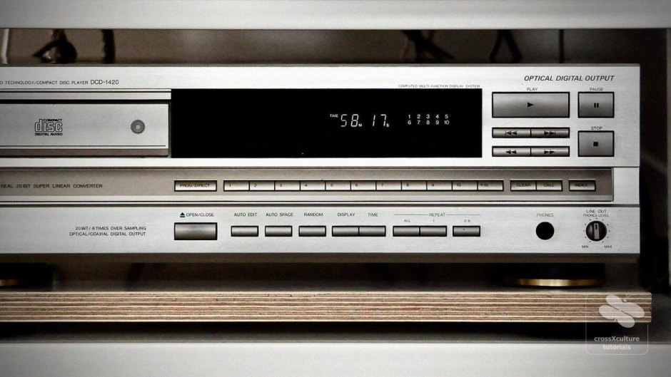
To have the most options, make sure that your CD player comes with a digital coax output in addition to the more common Toslink connector, as well as RCA/cinch, of course. The Denon DCD-1420 player shown below was rather pricy in 1989. A look inside shows that the parts used in its construction are of decent size, however, it also reveals that more could have been done in terms of power supply, shielding, tray design, etc. The player would most likely be considered mid-Fi by modern standards. One thing that I enjoy about it, is the fact that it is the only device for which I have a remote control. This means, I can pause and play back music as I please, without having to constantly get up. I would like to say that I can also skip between songs, but, because of its advanced age, the small task of skipping titles has long since become a giant leap of faith.
13. Digital cables

There are no absolutes in life, and knowledge is by far the biggest hindrance to continued learning. Because only if we challenge established beliefs can we be sure that they still hold true in our time. After all, the Bahamas were discovered in a period, when Europeans had decided that the earth was flat. Exploration needs a playful mindset that favours personal enterprise to established fear. The rewards can be quite bountiful, indeed.
When I set out to purchase a digital cable, I wanted to make sure that the signal coming from the CD Player was conveyed to the DAC in as pure a fashion as possible. I ordered a high quality fibre optics Toslink connector, as well as one four-times shielded cable of RCA/cinch coaxial standard for comparison. Prior to listening, I was convinced that the light pulse connection of the Toslink would present the purest result. To my surprise, this was not the case. Instead, the music sounded rather two-dimensional and flat, sticking to the speakers rather than being presented in the room. In the combination of Denon DCD 1420 and Cambridge DAC Magic, I found the Toslink connection to be less appealing to my ears than running the signal via the CD player’s own internal DAC. I did some research and found that this was a common phenomenon, possibly due to the quality of the two electro-optical converters involved.
In contrast, the RCA/cinch coaxial connection sounded better than the internal DAC, right from the start, even with the volume adjusted to a lower level. The music was immediately more engaging. However, in longer listening sessions I noticed some unpleasantness in the highs and some issues with the phantom center which comes from mono signals in the recording and should be fairly wide in scope. Although digital signals are claimed to be free from interference, because of the way they are transmitted, the sonic signature of the issue was familiar to me from HF distortion, e.g. to be found on power cables. I consequently started experimenting with ferrite clamps. First, I attached one clamp and moved its position along the cable, looking for sonic changes. Although I had some better and some worse results, none was actually pleasing. I then brought in a second ferrite, and, placing them both on opposite ends, finally had the sonic coherence that I had previously been missing.
The picture below shows a four-times shielded cable of RCA/cinch coaxial standard that I confectioned with a Viablue cable sleeve and two ferrite clamps. The cable sleeve has not been attached for optical reasons. I found that larger ferrite clamps have a better effect on sound, but with their growing outer diameter, the inner diameter also became larger. The cable sleeve has helped me to bridge this gap. Considering the amount of building material in use, the fully confectioned cable is still very affordable, especially in comparison with ready-made solutions.
14. DACs
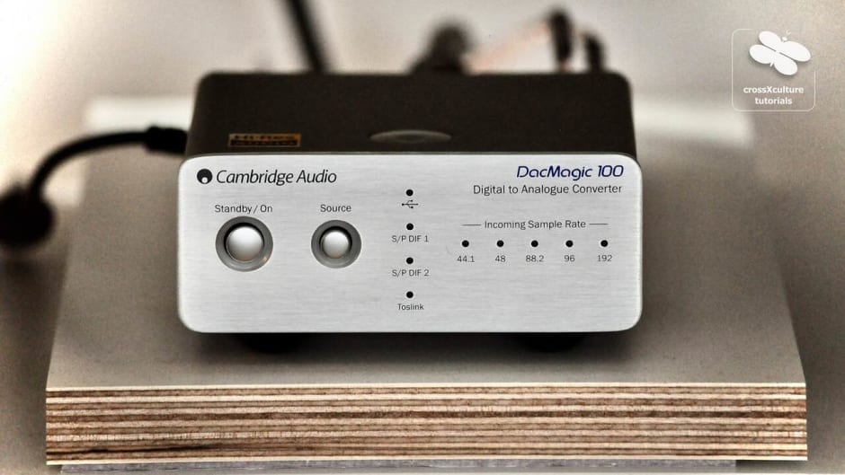
There certainly is ‘magic’ in a DAC, not just in a Cambridge Audio “DacMagic 100”. A DAC is needed to convert digital signals coming from a CD player, a streamer, a laptop or a PC, and possibly many other sources, into an analog signal that can be processed by an analog pre-amplifier or similar device. As the digital signal is an approximation of an analog signal, there are some calculations involved. Finally, there is some foresight and sonic calibration necessary in the analog segment of the DAC to match the DAC’s output stage with the receiving device.
The magic comes into play, when we hook up our DAC to a high-quality CD player. Because in this setup both the bit depth and sampling rate of the medium are given facts. The question at hand being: Will the external DAC outperform the CD player’s internal DAC, and in which way? Granted, you probably have to be an audiophile nutter to enjoy this sort of challenge. But, boys will be boys, and that is arguably good as it is. Other people sit for hours to pull fish out of the water, only to throw them back in.
There are better DACs than the Cambridge DAC shown here. However, it is good value for money and did receive a favourable review from Ken Rockwell which should mean something. This being our first DAC, the small investment seemed high enough at the time. The DAC offers two coaxial, one Toslink, and one USB socket. The USB processing, especially, is said to be among the best in the market. Hi-res audio processing is possible, up to 192kHz. Normally, the adventure would end here, but you can probably already guess that it won't.
15. Power supplies

Even experienced audiophiles will at times state that acoustic treatments to the room provide the most significant foundation for a HiFi system. However, while this surely can be a significant corner stone, I find that one small thing is overlooked in this statement, and that is the effect of power on our system. If I was to identify the most significant contribution to a system’s sound, power would be first on my list. If you take away the room, you will still hear sound, but if you take away the system’s power -
In steps 1-5 of this forum, the significance of power on the sonic nature of our HiFi-system has been described at great length. It is not surprising, therefore, that internal and external power supplies will have a similar impact on a unit’s ability to perform. Although the amount of power needed at any given time is relatively small for most units, especially when listening at 70-80dB indoor volumes, a power supply’s ability to deliver ultra quick, resonance and interference free electricity in the end will make the difference between our system moving towards High End or remaining stuck in HiFi.
A few weeks into listening to the Cambridge DAC, I noticed that the music’s highs seemed a bit tin-like and unrounded, e.g. on acoustic guitars, while the bottom end was lacking in natural punch and fullness, e.g. on lower piano keys. Later, while running some tests on the quality of electricity in our house, we noticed some regular spikes and general noise floor emanating from the switching of the Cambridge DAC’s external power supply, basically an unforgivable oversight for such an important part of our system. Therefore, against the manufacturer’s advice and warning, it was high time to make a change.
The power supply shown below was brought in to replace the cheap plastic China-made trailing edge transformer that had been found to inject local distortion into the whole system. With the new power supply, the sonic signature of the DAC changed from edgy and light to smoother and more balanced. Low piano notes now have a more satisfying punch and noticeably slower decay, much like on a natural instrument.
16. Loudspeakers
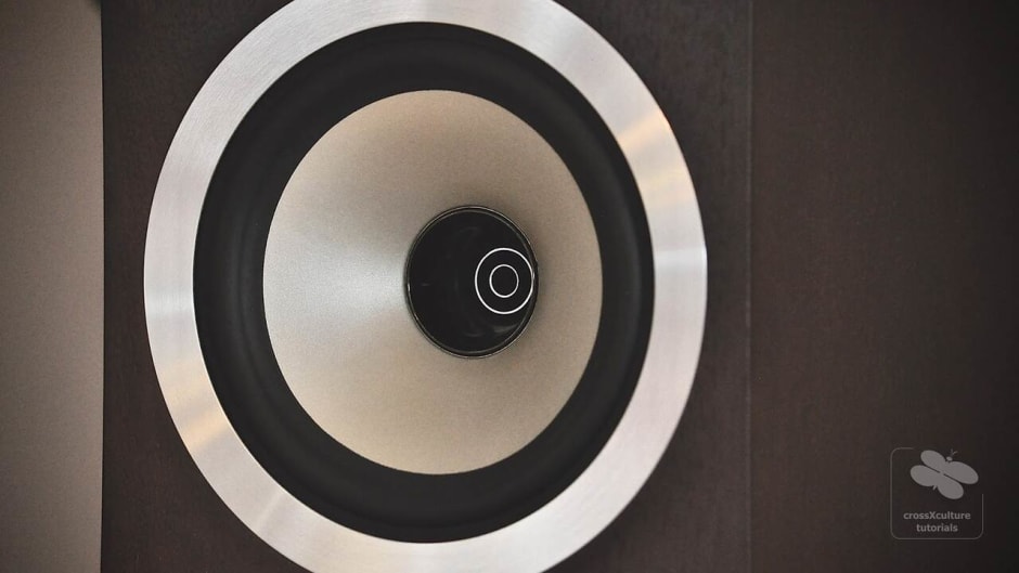
It is probably fair to say that there has been a fascination with loudspeakers right from the very start. Not so much with the technology behind them, but simply due to the fact that they can reproduce sounds of familiar things without being the thing themselves. For example, a loudspeaker may reproduce the sound of breaking glass, without being made of glass or shattering in the process. It may reproduce the clanging of hard metal, without being made of metal or clanging against anything itself. And, most importantly, it can mimic the sound of voices and instruments, a discipline in which human ears are especially sensitive and therefore critical. Even on people with emerging hearing disabilities, the voice level frequencies are usually among the last to go.
While attempting to sound natural and accurate in their reproduction of music, most types of loudspeaker are first and foremost entertainment devices, and as such, they need to be able to survive on the entertainment market. As our understanding of this market and our behaviour as consumers changes, so do the design choices made by the manufacturers. Loudspeakers today look rather different from those made in the seventies. While modern designs tend to be tall, slender and cool looking, their older cousins were often wider and stubbier with warm looking wood finishes. However, these are just the visible features and would be alright, if it was not for another trend, namely that of the infamous target group analysis.
Let’s face it. Well-engineered speakers, and the electronics needed around them, are by no means cheap. Manufacturers are therefore facing a rather mature customer group that has the space, time, and available income to purchase up-market loudspeakers. If income tends to improve with age, sadly our hearing often does not. It could well be argued that the two curves are diametrically opposed. Hearing loss affects both our ability to discern high notes, as well as our sensitivity to low volumes. Consequently, in A/B comparisons, the speaker with the loudest high notes will, more often than not, get to enjoy the ride home. Sadly, this type of speaker will have a life-long imbalance when it comes to natural representation, an obvious weakness that all future owners will have to come to terms with.
Many things can and will go wrong at the point of sale. The speaker that sounded great in the shop, might not sound so great when placed into our own living space and hooked up to our system. The room, the furniture in it, and the electric synergy with our existing components will all affect the impression of sound. If possible, loudspeakers should therefore be tested and compared at home. Some dealers will be supportive and make such testing possible, however, there is a natural limit to this, and we might feel pressured to make a choice. The other option is buying loudspeakers used. Provided that the speakers are not broken on purchase, they will either sound great or can be sold again, usually for a similar or even higher price.
17. Spikes or absorbers

When placing acoustic equipment in a room, there are many factors to be considered that will have an effect on our equipment’s ability to perform and on the specific sonic signature obtained. One such factor is the platform on which our equipment is positioned. In a perfect setup, desirable frequencies will be supported, while unwanted resonances will be reduced. The only question being: How can we distinguish between the two?
Loudspeakers are the most obvious devices within a HiFi system from which both desirable frequencies and unwanted resonances are emitted. In many cases, loudspeakers are sold without the addition of a specific coupling to the ground, and this does make sense, as the manufacturer has no control over the environment in which their product is going to perform. While it is often suggested that loudspeakers should be placed on spikes, to improve their sound, spikes will have a very specific effect that will only work, if the conditions are right.
For maximum frequency and resonance control, a loudspeaker should have a stable stand. To achieve this, the speaker’s weight is at best distributed between three or four couplings to the ground. If four couplings are used, at least one coupling must be height-adjustable to avoid wobbling. If three are used, they should be positioned relatively far apart to assure a stable stand. Among the many couplings conceivable, three types are the most common: spikes, anti-spikes, and absorbers.
In our own listening environment, I had first positioned the speakers flat on the hardwood floor, using non-height-adjustable 1mm felt pads. The sound was solid, but high frequency resolution was poor. The introduction of height-adjustable spikes and coasters brought instant clarity and direction to the music, but it also destroyed some of the homogeneity. Consequently, for quite some time it seemed to me that I had to make a choice between a well-balanced sound and maximum clarity. The spikes coupled the speakers so well to the ground, that the hardwood itself was in resonance with the speaker. To decouple the speakers from the floor, different methods and materials will work, also depending on the desired listening volume
18. Racks and resonances

Resonances play an important role in placing acoustic equipment in a room, not only when dealing with loudspeakers, but also on the devices that are used to drive them. Where they occur, they negatively influence a unit’s ability to perform according to spec and thereby change the sonic characteristics of our whole listening experience. Well-designed HiFi racks will help to keep both resonances and electric interferences at bay, however, not every good looking HiFi rack is acoustically ideal (very few are). It therefore makes sense to have some basic understanding of the subject.
A typical ‘old school’ HiFi system will probably consist of two or three sources, a pre-amp, and an amplifier. Each device is equipped with at least one power supply. Many high-quality power amplifiers will even have one large power supply per channel. In our current system, there is one power supply in the CD player, one on the DAC, one in the turntable, two in the pre-amp and two in the amplifier, bringing the total number to seven. Each power supply is humming at 50Hz. The low vibrations are affecting both the device itself and all adjacent devices. Other resonances result from city traffic, industrial activity, people walking nearby, household appliances, etc.
Although it may be argued that all HiFi units will benefit from resonance free placement, some are especially prone to instability, such as turntables and CD players. On turntables, any physical impulse coming from outside or within will be layered onto the audio signal and lead to inaccuracies in playback. On CD players the effect is not much different. Although some people argue that digital signals either work or don’t work, the effect of resonances can be heard in sonic brightness and harshness. If you have ever had an ageing CD player that would on occasion grab a CD slightly off center, you are already familiar with the effect, as before a CD skips, the music first becomes thin and strained.
19. Speaker position

Since very few audiophiles will have the privilege of building a dedicated listening room around their set of loudspeakers, both speaker size and position will need to be adapted to the space available in the household. In many cases, the chosen listening room will need to serve other purposes that are of equal or greater importance. Typical rooms for placing HiFi equipment are: living rooms, studies, dining rooms, etc. Judging from my experience in forums, many typical man-caves are even located in the basement. Be that as it may, there are a few simple rules that will help to enhance the acoustics in any environment.
Firstly, let’s get acquainted with the terminology: Seen from the listening position, the wall behind the speakers is called the front wall of the room. The wall behind us is the back wall, and usually there are two side walls to complete the room. As we have seen earlier, in ‘Spikes and absorbers’, speakers should be placed on a firm stand to prevent them from wobbling. The minimum distance to the front wall should be at 70cm, measured from the front of the speaker drivers to the front wall. The optimum distance should be at around 1/5th of the depth of the room. This means that on a five meter room, the speaker front should be placed at around 1,00 meter distance to the front wall.
The distance to the side walls should not equal the distance to the front wall. This is measured from the speaker’s axis and should be at least at a ratio of 1:1.3. To minimise the effect of room modes, our ear’s listening position should also be at least 1/5 of the room’s depth clear of the back wall. Moving both speakers and listening position closer to the front and back walls will usually enhance lower frequencies. For optimal imaging and sound stage, the distance measured between the speakers and the distance from each speaker to the listening position should be at least the same, in order to form an equilateral triangle.
When floor and ceiling do not provide a damping effect, any room can become quite hollow sounding. Placing a rug in front of the speakers will help take the edge off of the reflections. Very few speakers will sound well with their front aligned with the front wall, or toed in to stand on axis. Now is as good a time as ever to begin experimenting. What to listen for? If placed well, you will experience a seamless three-dimensional stage that has both depth and width extending beyond the physical position of the speakers. I am currently running two vintage systems, of which one is placed in the living room and the other in my office. In both cases, I have had to make some concessions to the multiple functions of the rooms. However, given some time and effort, I have managed to produce a quite realistic and wide stage impression that extends well beyond the speakers. I know that I could do better, if it were possible for me to move even further into the room. My current distances to the front walls are between 80cm and 90cm with a slight toe in, in both cases.
20. Types of loudspeakers

There are many different types of loudspeakers on the market. They range from horn-loaded designs to transmission lines, from 4-way via dual concentric to full-range. Each type has its own characteristic signature that will have benefits in some applications and disadvantages in others. To choose the best type of speakers for our lineup, we will need to consider the size of our listening room, as well as the types of music that our speakers will be mostly playing. While listening rooms will range from large to small and interior surfaces from absorbing to reflecting, our choice of music may similarly range from a preference towards natural instruments to electronically engineered sounds, from homely studio atmospheres to huge live venues.
If our listening position is at relatively low range, a speaker’s ability to perform well at high volumes will be less significant than its capacity to provide time and phase alignment at a close distance. If our preferred music is mostly that of studio recorded natural instruments and voices, our speaker’s ability to recreate the precise studio atmosphere will be more appealing to us than its ability to highlight the types of base lines found in artificially designed effect sounds that are found in movies and electronic music. If we have the necessary space to experiment with the positioning of our speakers, we will probably find that nearly all types of loudspeakers offer enough bass extension to perform well, even without the aid of additional subwoofers being placed in the room.
Horn-loaded speakers are among the oldest variety of speakers, dating back to a time when electronic amplification was not yet available. The amplifying effects of animal horns and conches were used for public address, even before music was recorded. Anyone who has heard announcements made over a public address horn will understand that horns cary some frequencies better than others, thereby changing the natural tonality of the addresser. Today, horn-loaded speakers are mostly used in settings where music needs to be cast at high volume and over long distance, such as live concerts. Similarly, if live concerts played at high volumes are our preference for home listening, horn-loaded speakers might be our our choice of medium.
Today, the most common type of loudspeaker for home use is still of a relatively unexciting box shaped design with moving coil drivers that are made of paper or similar light weight materials. This design provides lots of freedom in terms of room placement and usually offers specialist drivers for each frequency range to assure for accurate reproduction of sound. Since the moving components of moving coil driver designs are relatively heavy, there is at least some unintended time lag involved when bringing them up to speed and slowing them down which leads to a smothering of frequencies. For those of us willing to experiment with more nimble designs, both planar magnetic and electrostatic speakers may present interesting alternatives in sound reproduction.
21. Silencing open inputs
The first time I read about RCA caps was in the instruction manual of the Restek V1 preamplifier. In this it is explained that all unused RCA input circuits must be shortened to suppress noise potential coming from high frequency radiation. It is stated that the unit could not otherwise fulfil its specifications in terms of total harmonic distortion and signal to noise ratio. Not knowing what to make of this information, I was relieved to find that they come in packs of a dozen and are relatively inexpensive to purchase new.
Despite the Restek V1’s gold plated inputs, I decided to purchase the caps from a Chinese importer called Audiocrast. The base material is brass which has then been rhodium coated. These plugs were much better rated than their golden equivalents, otherwise I would have attempted to lessen the effect of material transitions by using the same contact material as the inputs.
On the Restek, the plugs have the effect of making the noise floor dead silent on all sources. This is less pronounced on the phono stage where the input signal is much lower than that coming from the DAC. Listening to Diana Krall’s ‘Turn up the Quiet’, the fading out of the studio’s ambient noise is much more apparent with the plugs than it was before. This means the system’s noise floor is far lower than that of the recording studio. I also can appreciate listening at higher volumes much more than I did before, simply because the music stands out more prominently from the background. I especially enjoy the effect the plugs have on stage depth, which has just become a little more realistic. Restek was not wrong in suggesting the use of the plugs. If your system is capable of great sound, this little add-on can well be considered an audio essential.
22. Audio Cable Position

When I began my literature studies in winter ‘94, this was also the start of a long period in which I did not have the time nor means to set up and maintain a proper audio system. Two years into my studies, I had sold all components of my existing system to friends in order to shore up some much needed cash. The last item to go were two 35kg ‘Fidelity 425’ transmission lines that I had built by myself, using the parts and following the construction plan of a small German speaker manufacturer by the name of Mainhattan Akustik—now no longer in business—that was based in Hainburg, near Frankfurt. From part of the earnings gained from selling my system, I bought a Denon ‘F70’ midi system including bookshelf speakers. There was no comparison between the two systems, of course, but the Denon was much easier to place in my small student dorm.
When, many years later, I was sitting with my wife listening to music on my old F70 midi—ever so often getting up to position the speakers for them to produce better sound—I told her about my former passion and asked her if she would be interested in us setting up a proper system once again. My wife being into music herself in many ways immediately liked the idea, and a few days later, we were on the way to Bavaria to pick up a used pair of Canton Vento 890 DC floor-standing speakers. We were still on a tight budget and the Ventos seemed to have a good quality to price ratio, especially when bought used. I must confess, that during my long absence from HiFi, I had lost track of the trends and names of the industry.
The Vento 890 DCs improved the sound at our home significantly and were soon fitted with an Apart Audio ‘Champ 2’ PA amplifier and a pre-amplifier by the same manufacturer. Coming from the Denon midi system, it was not very difficult to improve the sound, and we were actually happy for a few weeks, until I invited a friend over whose father had been into HiFi and High End listening. We could see the confusion on his face, as he was pacing up and down the room, saying that he could not recognise anything relating to proper sound as he knew it. However, not being an expert himself, he did not know why. He was unsure if perhaps his ears and age were to blame, but knowing what I know today, I am feeling a little ashamed that I even asked him to come.
When I re-entered the sphere of HiFi listening, I was not only starting over, I had also forgotten much of what I had already taught myself from experience during my active years. That our friend left our house in bewilderment was due to the fact that most of steps I have described in the ‘High Fidelity’ section of this blog were still or again unknown to me. And although much of the equipment we had bought was pretty hopeless in terms of sonic integrity, we could have taken steps of improving the sound which had nothing to do with the devices themselves. Sadly, the first thing that we should have done would have been the easiest by far. In fact, it is so obvious that it is actually surprising it should have taken me until recently to find this out.
I had often read in HiFi forums that the cables connected to our systems should neither cross nor touch. And while this sounds like a pretty straight forward message, I never paid much attention to it. Partly, because I had no idea what the effect of crossing or touching wires was, and partly, because I always figured that I could do this later. Looking behind our system, preventing wires from touching or crossing always looked like an impossible task to me. What they should have written was: “Your wires may not touch or cross, because it will make your system explode.” While this is not true, of course, it would have saved me many years of getting only half the joy from our equipment.
What is meant is that cables carrying the primary source signal via separate channels must neither cross one another nor touch when running in parallel, as this will smear the soundstage, lead to signal loss—noticeable in a lack or significant shortening of transients—and to signal compression. They should also not touch or cross the power cables of the devices as this would have similar a sonic effect and additionally bear the risk of introducing network modulation into the audio path. Cables running from preamp to amp should also be prevented from coming in contact with other cables. The closer to the music source the cables are located, the more pronounced will be the effect of correct vs. incorrect placement. Finally, speaker wires should be of equal lengths per channel and not be running in parallel or touching power lines, other cables, or antennas. If your system is up to it, and if you are looking for the last bit of perfection, you might want to consider raising your speaker wires off the ground as a final measure.
I will dare to make a prediction—however, do feel free to let us know in the comments below, if you should not be able to confirm this on your own system: Following these optimisations, your system will sound at its best, based on the equipment that you have put together at this point. If there are sonic issues that still need to be resolved, you will be able to discern them more clearly than before. If the position of your cables was the most significant issue, you will be very pleased. Enjoy.
Note 31 Jan 2021: Wires carrying signal should not touch. This is most relevant closest to the signal source. On turntables this includes the wiring from the headshell to the cartridge. Since this is often overlooked, there is lots of sonic potential in getting this simple first step right. I came across this phenomenon by accident today, when I re-mounted a headshell to find that the sound had become substantially worse. I separated the wires and the sound became superior to any I had heard from this turntable. I consequently went to our other system and separated the wires on this headshell to the same effect. Considering that both cartridges had been mounted by professionals, it shows how little even professional people understand about setting up systems.
< 21. Silencing Open Inputs | 23. Sound Stage >


23. Sound Stage
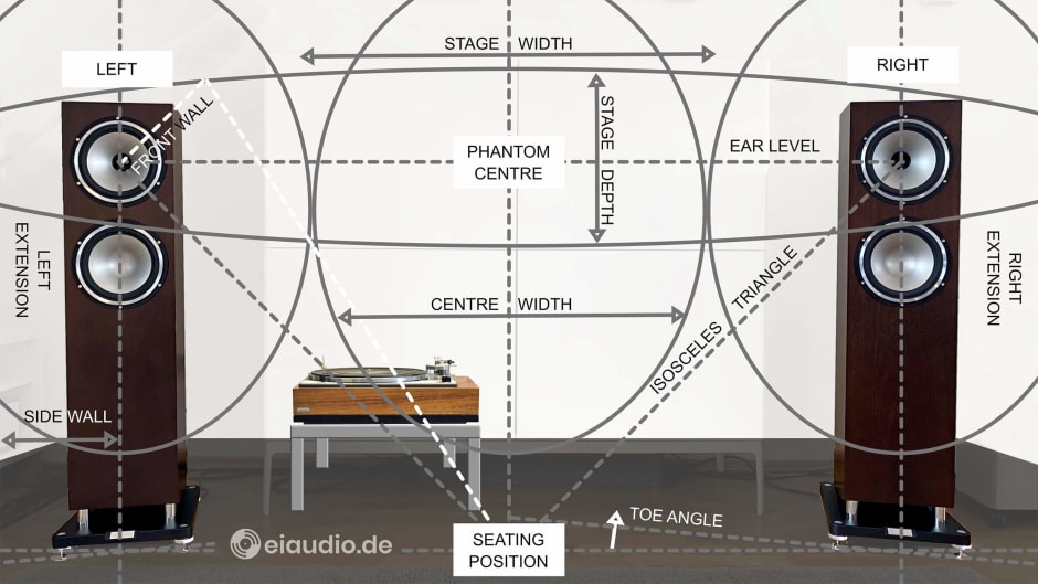
The term ‘sound stage’ describes the acoustic impression of width and depth that resembles a live-stage setting, observed from the position of the audience. It is mostly used in the context of two-channel stereo setups but can also be found in three-channel stereo and two-channel mono discussions. A solid sound stage is the result of many important and correct decisions when setting up a HiFi system, and it is difficult, if not impossible, to achieve this without observing most of the ground rules laid out in the twenty two points of the ‘High Fidelity’ section. The sound stage is a result more than it is a ‘thing’ to be done, but in order to describe it and identify flaws in it, we need to make sure that we agree on some basics.
The picture shows the current 2-channel setup of our Hafler XL280 and Tannoy XT8F system. The loudspeakers are positioned 90cm from the front wall, measured from the front of the driver and the center axis of the speaker. When discussing the distance to the front wall, we refer to the distance between driver and front wall, rather than the back of the cabinet, as this changes with the dimensions of each new speaker. The reason for this method is simple: It is the driver that reacts with the room, not so much the speaker’s cabinet. Based on the circumstances found in our specific room, the distance between the speakers results in only two meters, again measured from the driver’s centre axis.
We have positioned our listening chair to assure that the listener’s ears are at level with the tweeters, which is usually the manufacturer’s advised position. Since the Tannoy speakers are of coaxial (or dual-concentric) design, tweeter and midrange share the same axis, making the correct level of the ears even more attractive. Furthermore, to assure ideal listening conditions, the distance between the ears and the drivers should form an isosceles triangle with the distance between the speakers. As in many domestic environments the distance to the listening position needs to span the full depth of the room, it is advisable to place speakers and listening position on opposite sides along the wider walls of the room. This setup offers the additional benefit of minimising first-order reflections from the room’s side walls.
In our setup, we have turned the speakers towards the listening position by 5 degrees. The resulting angle is called ‘toe-in’. Depending on room conditions, speaker distance, and speaker design, more or less toe-in will be preferable. It is therefore advisable to begin on a slight toe angle and to increase and decrease the angle while repeating the same song. This is most quickly achieved with a friend, or even better two friends, one at each speaker. While changing the angle, it is important to maintain the exact distance to the front wall. Even one centimetre of forward or backward movement will have a strong impact on sound.
There should be three discernible positions from which the music emanates. The left speaker, the right speaker, and the centre between the two speakers. The centre image results from mono signals in the recording, and since there is no visible speaker in this position, it is often called the ‘phantom’ centre. Speaker toe-in and listening position should be such that the music creates one seamless stage, panning from left to right. If there are holes in the stage, the speakers probably need more toe-in. If the stage is too narrow or compressed, the toe angle should be decreased. When positioning speakers in this way, you are looking for believability, i.e. a position in which the stage appears to be most natural.
In most forums, the vast majority of people discussing the merits of equipment have not even taken this basic step to assure fidelity. What they are discussing, therefore, is a random overlapping of frequencies. This becomes clear when they post images of their rooms and their setup. Based on their observations, they proclaim that speakers matter or that amps matter more. Little do they know that moving the speakers a few inches will transform their systems more profoundly than any new speaker or amp could ever do for them. No wonder, they cannot hear the difference between HiFi racks (in their ability to absorb micro-vibrations), or the merits of different cables (in their ability to protect and time-align signals), for as long as simple acoustic laws are not being observed.
If the speakers are set up correctly, listeners will be able to discern the three positions, but they may find that the music does not free itself from the speakers, so that the width of the channels, or that of the centre, or both, is very narrow still. The channel width can be fixed by making sure that ground potentials between the HiFi units are minimised. This is usually done by checking the polarity of the AC plugs. This is however not applicable in countries with fixed polarity plugs, unless you have a faulty AC outlet, power cord, or your unit has been meddled with internally. The centre image becomes narrow, for instance, if electrical interference affects the audio signal, either through HF interference, or through touching or crossing RCA/cinch interconnects. When the signal is received in a pure and clean fashion, the centre will be wide and pleasant.
When music is recorded, natural instruments such as piano, guitar, and drums are picked up indirectly with the use of microphones, rather than being directly connected via the use of cables. This means, music is captured in two ways: Directly from the source of the signal, and indirectly, when reflected from walls, floor, ceiling, and objects in the room of the recording. When sound waves are reflected, they are delayed and/or inverted. Our brain calculates the amount of delay and inversion and from this derives a sense of room dimension, material property, signal location, and distance. In a two-channel setup, it is therefore possible to hear music coming from positions to the far left and far right of the actual speaker positions. This is called stage extension.
On a proper setup, we can also sense elements of music that seem located nearer to us and elements that seem to be further away. The impression of stage depth is the result of recording choices, but the recreation of this stage in our listening environment is just as much dependant on our choices in setting up the system. Speakers that are pressed into the corners of rooms or standing too close to the front wall will not be able to deliver the same intact quality of imaging as speakers that are placed properly. And as timing has an electrical as well as acoustic dimension, proper speaker placement will enable you to identify HiFi units and cables that have frequency dependent timing issues.
I hope to have explained my findings well. Although I have read extensively about the subject of soundstage in recent years, the image and explanation I have shown here is based on my own findings as audiophile listener. If you feel that an important aspect of sound stage is missing from this description, I would welcome your input. Feel free to leave your comment below or contact me directly.
Enjoy your music.
24. System Grounding
Differences in ground potentials on interconnected HiFi units are arguably the most significant cause of signal infidelity in sound reproduction and constitute one reason for the manufacturer’s THD levels not to be met. Ground potentials may vary due to small amounts of voltage leakage from the transformer within a unit, or similar issues, but they are even more likely to differ between units, due to internal design choices and—most importantly—due to differences in the grounding that is provided by the AC power source. Furthermore, external antennas and installations from cable network providers constitute additional noise sources.
While it is true that the power transformers in our HiFi units regulate the AC current supplied from the wall socket and isolate the chassis, transformers will unavoidably leak small amounts of current, resulting in chassis voltage. Measured on our Harman Kardon HK730 receiver, for instance, the current leakage was confirmed as varying between 0.3 and 0.6 volts. Transformers in audiophile units will most likely be of the conventional linear type, with an iron core and wound primary and secondary coils. Since this winding has a direction by definition, the input resistance is likely not the same at both primary ends. Since in AC power supplies only the phase oscillates, e.g. between +230V and -230V in Germany, there will be a different transformer input resistance depending on which end is driven and different levels of leakage voltage, even if the resulting secondary voltage is the same.
On an all-in-one HiFi unit, slight deviations from ground level are normal and will not affect the sound, but when two or more units are interconnected, differences in chassis potential will be harmonised via the RCA/cinch connectors and form a ground loop with the house installation. It is a loop, because the HiFi units are connected with each other on two levels: the power supply and the RCA/cinch connectors. And even in cases where the noise itself is not audible via the speakers, the integrity of the music signal is compromised, because it carries the additional burden of energy leakage. Human ears tend to be unforgiving to technical noise, perhaps, because it is not a natural occurrence to which our species has had millions of years to adapt. To address the issue of varying chassis potentials, the professional audio industry has long since introduced symmetrical and optical connections that do not connect chassis grounds. There are, however, acoustic downsides that result from the addition of couplers which have made most audiophile listeners shy away from this technology.
In audiophile circles, therefore, it is common practice to minimise differences in ground potential between the units by turning the power plug of each unit and comparing the resulting audio output though listening tests. When there is minimal difference in potential between chassis, the music will sound fuller and lusher with better imaging and tonal balance. When there is greater difference between potentials and more leakage current is carried via the RCA/cinch connectors, both lower bass and transients will be compromised with the tonal balance leaning towards brighter and yet somehow duller highs. To identify the lowest amount of difference, it is important to start from a minimum number of devices and then check the polarity of each new unit. Companies such as Oehlbach offer a polarity tester, however, I have found my ears to be the better judge of polarity and have at times disagreed with the unit’s findings. In recent years, I have achieved the most satisfactory results by checking the polarity by ear.
Since polarity makes such an audible difference on grounded units that are connected with RCA/cinch, finding out the preferable polarity has become a common first step in setting up HiFi systems, especially among vintage audiophiles, who do not follow the path of correcting the signal retrospectively, by running it through a digital sound processor (DSP). In fact, when signal integrity is maintained throughout the unit, the sound will be superior to retrospective DSP corrections, simply because a DSP cannot correct what is not there and will in the end be kept busy filtering and flattening the effects of a hum or of HF interference, without being able to differentiate between the signals. Maintaining signal integrity is similar to fly fishing, whereas a DSP is more the practice of throwing dynamite into the stream. Sure, skilled people will catch fish either way, but I doubt that the pleasure of the achievement will be the same.
My initial reason for embarking on the subject of system grounding was of a different nature, however. For many months, I had a humming issue on our Philips turntable that I could not explain. I had already removed the antenna cable, optimised system polarity, and still the humming continued to be present at a level that was highly annoying. The turntable signal was compromised to the point where it was lacking both dynamics and soundstage. Since I could not find the solution, I decided to write about my sorrows in a vintage audio forum, describing our system setup from power sockets to our Martin Logan electrostatic speakers. The response was imminent: Where did you plug in the power cords of the speakers‘ high voltage supply?
The mistake I had made by plugging in the speakers into wall outlets (right where they stood) was instantly clear to me, but only with the little nudge from a forum member. By using separate sockets, I had created a difference in ground potential between our high voltage powered Martin Logan SL3 speakers and our B&K ST140 amplifier that was now trying to harmonise potential through the speaker cables in the form of an audible hum. Since this only occurred when phono was selected as input, I had simply failed to understand the situation. With hindsight, the reason for this is simple: since phono is more sensitive to interferences, this was the most obvious point of the error to become visible. This does not mean, however, that other sources were not affected. Connecting the speakers via the same PowerStar rail as the rest of our system brought phono noise down by an audible 70%, at least.
25. Audiophile Room Cooling
When outside temperatures are rising during the summer months, many audiophiles are beginning to dread the increase in noise floor that results from various methods of keeping cool indoors. For many of us, our listening hours fall into the evenings, a time when the streets and buildings are still hot from the day. This is when the electrical noise on power grid and the physical noise from outside slowly subside, normally giving way to endless hours of listening pleasure. However, this pleasure is relatively short lived, when the listening room becomes too hot for comfort.
In very few cases, the ideal listening room will be located in the basement of your own house, on which high outside temperatures have little effect. Basements tend to have low ceilings and concrete walls that will pound back bass frequencies in an unbecoming way. No, most proper listening rooms will rather be situated above ground with wooden or masonry walls. And in such an environment, temperatures can become quite high, especially in an apartment or under the roof of a building. While perhaps also not ideal in terms of bass performance, a listening room under the roof can be advantageous to sound, because of the relative absence of parallel walls.
To make matter worse, many audiophiles will be running HiFi gear that produces more heat than regular consumer products. Tube gear, for instance, radiates far more heat than solid state devices. But even when operating solid state equipment, audiophile amps tend to be oversized MOSFET beasts running in class A, rather than being more power efficient class B or D designs. Actually, audiophile gear often only sounds at its best, once it has reached full operating temperature. And, in many cases, this means you could literally fry an egg on them.
The most economic and ecologically friendly way to cool down a room is to simply open the windows, but in many urban locations, this will raise the noise floor in an unpredictable way, bringing in sounds from cars, planes, trains, and from people walking by. In rural areas, the noise might come from the wind in the trees, from birds, etc. but also from the local traffic. I think most audiophiles will agree that a closed window is an effective way to drown out sound coming from outside and will be preferred.
If the windows cannot be left open, cooling must ultimately come from some apparatus that is placed or installed in the room. Some buildings have air conditioning installed into the walls, and, in most cases, this will be the best option to address cooling, because this method also extracts excess moisture, a fact that makes any temperature more bearable. However, air conditioning is also the most expensive solution and, from an environmental perspective, not without concern. A simple cooling fan would present a cheaper and more sensible choice, when no air conditioning has yet been installed.
If you have ever listened to music in a room where a cooling fan with open propeller is running, you will already know that this will quickly make chop suey of our musical experience. There are few audiophiles able to tolerate the presence of a running fan in the room, perhaps with the exception of an ultra-slow and silent ceiling fan. No, there must be a better solution to keep the listening room cool in summer, one that does not interfere with the music so much. At least this is what I was thinking, when I set out to purchase a cooling device that would not spoil the fun of listening.
At the time of writing this, air movers without open blades have not yet been popular for a long time, and yet, they help to solve the problem of rotating blades interfering with our music. While they are mostly referred to as bladeless fans, this definition is not strictly accurate. Their rotors are rather smaller and encapsulated by the housing, with the air being moved through one or more ducts for speed and direction. Rather than producing a frequency of air-compression and expansion, the resulting air flow is seamless and calm. This non-pulsating quality is preferable in audiophile settings, even if the fan itself should have a similar dB-noise rating as a fan with exposed blades.
The model shown here stands representative of a whole range of bladeless fans from various manufacturers. It was bought at the German DIY store and REWE subsidiary ‘Toom Baumarkt’ and offers a host of features that make it a decent companion for extended music listening sessions. There are 9 air speeds to choose from, ranging from relatively silent to more noisy in operation. The good news is that levels 3-5 will offer sufficient airflow for most applications, while still being reasonably silent. All levels offer decent reach into the room, so that the fan does not need to be positioned close to the listening position. Although the fan does not cast its breeze all too broadly, the angle should still be wide enough for an individual listening spot and can be increased by engaging the 90 degrees rotation function.
The tower fan comes with a remote control that can be fixed to the shaft via magnet, e.g. for storing or for strictly local operation. The remote turns the fan on and off, sets the air speed via plus and minus keys, engages the rotation and sleep function. It can also set a sleep-timer and has a button to jump to maximum airflow and back to the previous setting. With all these functions available from a seated position, wind speed and noise can be adjusted to suit the listening moment. Rock & Pop music will probably be more forgiving of noise than classical or Jazz music that are often more nuanced with lots of quiet passages. The fan’s hight is just under one meter and therefore very convenient for a seated position. The air is conveniently drawn up from the colder floor and then ejected into the room. The tower fan is Smart Life compatible and works with Alexa. This means it can be integrated with other Smart Life machines in the households and operated from the smartphone. Have a look online. Similar products are available from other brands and stores.
Specifications
- Maximum airflow: 22 cubic meters per minute
- Power consumption: 26 watts, 240 V, 50 Hz
- Standby consumption: 0.8 watts
- Noise level: 56 dB, maximum
- Air speed: 4,6 meters per second
- Remote battery: CR2025, 3 V
- Year: 2020


26. Does vinyl sound better than digital sources?

The beginning of the 21st century saw an ever-increasing presence of compact and convenient digital technology in our households. Ever since the invention of the iPod, we have been able to fit an infinite amount of songs in our pockets. And streaming services such as Spotify, Tidal, and AmazonMusic, to name just a few, have provided universal access to a sheer endless selection of music at affordable prices.
While some people enjoyed the ability to scroll through an abundant list of choices without having to make a personal commitment, others were feeling lost and started missing the mutual aspect of the relationship, the connection between a band and its fans, that music once was. It may have been a natural impulse for these people to start being nostalgic about the pre-digital age, in which musicians and record labels could manage to make a living with relative ease and where the incentive was high to continuously create lots of quality content, rather than churning out 1-hit wonders based on click-bait algorithms and predominantly similar-sounding tracks.
Vinyl was a welcome refuge to those fleeing the effects of the digital madness. In fact, records stood for everything that streaming music did not: The medium was naturally limited in the number of songs that fit on each disc. During the reading of each track, the stylus followed a signal grove that contained a faithful analogue transcript of the acoustic event. Pauses between songs were visible as recurring patterns to the naked eye. To play a song or album, one had to physically get up from the sofa and choose one record from the available collection. And, in order to have quality music available, one had to become a discerning collector and strategically develop one’s taste in music.
Putting the needle on the record produced a crackling sound even before playing the first song, and it was possible to visually follow, appreciate, and comprehend the process. Turntables are transparent about their method of reproducing music. Unlike most digital equipment, where the music reproduction comes from an invisible and practically unchangeable black box, turntables have a personal character and will perform better with increasing know-how of the person setting them up. Choosing components, understanding the mechanics, eliminating vibrations, managing the electrics, and improving the electronics — all these factors contribute to the quality of sound. Turntables practically invite their owners to care deeply and to begin a journey of exploration.
Turntables that have been set up with proper care will sound very similar to CDs and other high quality sources, such as online streaming devices. They will not match the CD’s low noise floor, nor will they offer the dynamics available from modern digital formats. They will, however, produce a sound signature that is highly harmonious as well as a softer and more natural top-end that some listeners find to be more pleasant to the ears. Despite their intrinsically lower specifications, the technical abilities of turntables are perfectly sufficient for joyful listening sessions. Records that have been well-maintained will not produce lots of noise, either. Clicks and pops are rare and in any case secondary to the music signal. It is an urban legend that vinyl heads enjoy listening to record noise. If at all, they enjoy that last bit of unpredictability that the record has maintained.
Turntable sound quality is mostly compromised by poorly pressed or mastered records. In my own experience, modern vinyl productions often cause problems, because the mastering engineer did not understand the medium well enough. This often leads to sibilance or other distortion. With the growing demand for analog recordings and only few experienced factories available, the quality of pressings can be pretty dismal. Discs arrive warped, out of centre, or poorly moulded. 180 grams records are no guarantee that the quality is better. While records produced during the 70s mostly offered excellent durability and quality, modern productions sometimes seem to use lower grade materials and production methods, causing 50-70% of all modern records to be of less than ideal quality. In this context, it seems unfair that media sellers will refuse to take records back, even if the pressing is of a low standard.
Setting up a turntable to play music well is an art form comparable to fly-fishing. While it is surely cheaper and more effective to purchase fish from the deep freezer of a local supermarket, the sensation of accomplishment and the joy of consumption cannot be compared. Of the analog sources ranging from reel-to-reel via 8-tracks to compact cassettes, etc. only the turntable offers the optimum combination of longevity, convenience, and sound quality. And, while it certainly does not sound ‘better’ than digital sources, it will sound different from machine to machine and from owner to owner, thereby adding an exciting personal dimension to the otherwise arbitrary and perhaps even boring experience of canned music reproduction. Sophisticated turntable setups often say as much about their owners as they do about the quality of music.
27. Subwoofer Placement

Subwoofers are dedicated loudspeakers designed to support the main speakers of a Hi-Fi system in playing back the frequencies found at the lower end of the spectrum. When it comes to the placing of subwoofers, it is important to keep in mind that they do react similarly to larger loudspeakers so that many of the principles relevant in placing them remain the same. I have sometimes read in dedicated forums and on specialist sites that subwoofers allow for some liberty in placement, as the source of low frequencies is more difficult to locate for the human ear. However, this only seems to apply to a smaller extent and to very specific applications, such as the LFE (Low Frequency Effects) channel found on some home cinema systems.
The idea that a subwoofer’s position should not matter much stems from the correct observation that subwoofers mostly cut in somewhere between 100 Hz and 50 Hz, depending on the cut-off frequency of the main speakers, where the sound waves are already considerably long, while our ears are only about 17.5cm apart to detect the subtle differences in timing. And while this does make some sense, I wanted to learn more deeply about the exact wave lengths and started doing some research. Here is a table of some wave lengths that are typically associated with subwoofers. They are calculated at room temperature at an estimated speed of sound of 343.2 meters per second. Changes in ambient temperature, air pressure, and moisture will effect the speed of sound and can therefore lead to slightly different results:
Subwoofer Frequencies & Wave Lengths
- 35 Hertz (Hz) = 9.8 meters (m)
- 50 Hertz (Hz) = 6.9 meters (m)
- 60 Hertz (Hz) = 5,7 meters (m)
- 80 Hertz (Hz) = 4,3 meters (m)
- 100 Hertz (Hz) = 3,4 meters (m)
- 150 Hertz (Hz) = 2,3 meters (m)
The table shows that the relevant sound waves for subwoofers are between two and ten meters long. One could therefore come to the conclusion that these are long enough for the subwoofer location to become negligible. And yet, in real-life listening, I found that the source of the pressure often remains perceptible, especially on front-firing subs. While placement may not matter so much for subwoofers supporting movie sound, audiophile two-channel setups do benefit from ultra-exact positioning and mindful integration with the other speakers in the room. Due to this circumstance, the necessity for a subwoofer to be added to a system should best be determined as the famous English comma rule suggests: If in doubt, leave it out.
In fact, I have not yet heard a single Hi-Fi stereo setup using a single subwoofer that worked smoothly across a whole range of song materials without either exaggerating or smothering certain aspects of the music or giving away the subwoofer location. The general idea is: If you can hear the subwoofer, if it draws the least bit of attention to itself, your job in placing and calibrating your setup is not yet done. What further hindered me from an early entry into the subject of subwoofers was my own scepticism regarding the use of DSPs (Digital Signal Processors). While I have not yet used a top-of-the-line DSP myself, I have had the privilege to listen to professionally calibrated DSPs in action on a number of occasions and found that, unless the listening space was the driver’s seat of a car, similarly good, if not better, results could have been obtained through a proper selection of components and a better placing of these on the rack and in the listening room.
In my own experiments regarding the placement of subwoofers, I therefore decided that I would work without DSP, equalisers, tone controls, and loudness to listen for differences in sound. The only tonal adjustments would be made through the built-in attenuators on the speakers. The subwoofer to be used for my tests was our actively powered ‘Dream 2 Sub’, made by the Chinese Dragon Audio, or DA, in 2012. I had originally bought this to accompany our Shure ‘701 Pro Master’ PA speakers, and this was also going to be the combination of my test. The Shures had been fitted with a treble attenuator to reign in the horns in smaller listening rooms, and the DA Dream 2 featured an input volume control, crossover frequency adjustment from 20 to 200 Hz (sadly, non-scaled and possibly also non-linear) as well as a 180° phase-correction switch. All other results had to be achieved by means of positioning the components alone. No active crossover was used in the process.
In the very beginning, while doing research on loudspeaker positioning, I had often come across the proportional value of one-fifth (1/5). In these articles and videos it was suggested that setting up the loudspeakers and listening position at approximately one fifths of the room’s depth was a worthwhile starting point to begin with the fine-tuning. It seems that, due to the variations of frequency lengths and the overlapping of multiple frequencies, there were less likely to be audible peeks or dips in the critical bass area. Usually, the closer the speakers and listening position were moved to the wall, the more bass frequencies would begin to dominate the music. On the other hand, moving the speakers and listening position further away from the wall would have the opposite effect. Peter Englisch did some excellent work on determining more exact loudspeaker and musical instrument placement for bands that I will present in a later report.
The side walls also played a role in the sound equation. Loudspeakers should not be positioned in close proximity of the side walls to lessen the amount of side-wall reflections. The distance to the side walls should also not be the same as the distance to the front wall. It is sometimes said that a 1/3 deviation would be a good place to start. In a rectangular room on which the front and side walls are of different lengths, you might be able to achieve good results with 1/5 distance from the side walls as starting point for your fine-tuning. If this is not the case, gradually moving your speakers closer toward the centre axis might do the trick. In my graphic illustration you can see that the room has been divided into five squares in each direction to indicate the approximate starting points of speaker positioning. The first components placed were the left and right loudspeakers (LL and LR).
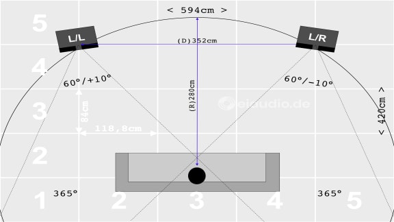
The illustration also shows the couch positioned so that the listener’s head is approximately one fifth away from the back wall. The left and right loudspeaker (LL and LR) have been toed in at an angle of ten degrees (10°) towards the listening position. Since the Shure 701 Pro Master were horn-loaded speakers calibrated to a 60° radiation pattern, a small toe-in angle was a good starting point. I have indicated the driver’s position with a black line on that side of the speaker and pointed to the Shures’ horn effect with a broken black line. Given the circumstances in my real-world listening room, I ended up with a narrower placement of the speakers and also positioned them a bit closer to front wall. This was a compromise between using the space as a listening room as well as a living room for the whole family.
The 1/5-point does not apply to all speakers or rooms. The Snell A-Series, for instance, prefers to be placed in close proximity to room walls and also may not work so well when toed in. When positioning speakers we are mostly looking for the position where the speakers click in with the room. Given some time and experience, this position can be found. I did find, however, that the large diaphragm Shures benefited from the rule, and so did our Martin Logan SL3 and the Snell C-IV speakers tested here earlier. And although we are in the process of exploring the placement of subwoofers, the correct placement of our main speakers needs to happen first, because the two are connected. Unless you are setting your system up to enhance movie effects, where the loudest boom might still be your preference, loudspeakers and subwoofers need to form one acoustic unit.
In placing the subwoofer, I was looking for the most audiophile placement option, on the basis that the term ‘audiophile’ means balanced tonality, joy and agility, nuance and instrument separation, and all this embedded in believability and homogeneity. As we shall see, changing the subwoofer’s position had a profound effect on all these factors, often to the point of killing the merits of the two-channel setup altogether.

I began my explorations placing the subwoofer to the left side of the right loudspeaker (S/R). Since our Hi-Fi rack occupied the space in the centre of the front wall, I could not choose a more central position. A first listening test unpleasantly revealed the subwoofer’s position and smothered the sound. Toeing in the subwoofer slightly did not improve the situation much on its own, but when I started moving the subwoofer forwards and backwards, I could hear the resulting changes with each centimetre. When the sub finally locked in with the room, I was surprised that it was nearly flush with the main speakers. However, from the perspective of the listening position, it was even protruding forward.
Before making my drawing of the room, I would have accepted that placing the subwoofer flush with the loudspeakers might produce the best result, as this would result in the wave signal reaching the listener at the same time, but drawing the radius around the listener’s head quickly revealed that a similar listening distance would have required a more recessed subwoofer position. It seems that the error in my visual assessment had been caused by the low toe-in angle of the main speakers that had already proven itself for better stereo separation and tonality. Why then did the subwoofer sound in phase when being flush with the main speakers? It seems that this may have resulted from a phase delay caused by the subwoofer’s built in active crossover and that bringing the subwoofer closer to the listening position had made up for this delay.
When listening to music in flush position, I could hear that bass lines had an actual story to tell and that they were created by multiple instruments. There were many layered and contrasting bass lines instead of just one bass. I enjoyed this increase of tonal nuance and musical insight, but I could still feel the sub’s pressure and force coming from the right, which made me feel dissatisfied and restless. This may have stemmed from the Shure speakers being fed the complete signal and naturally fading out where their role as PA tops demanded instead of being cut off by the active crossover as well. But since I enjoyed the tonality and musicality of the setup, I simply would have preferred to see one such subwoofer underneath each Shure speaker, perfectly phase aligned with the main speaker drivers to balance the image and maintain bass nuance. If I had had a second subwoofer at hand, I think this would have been my favourite position.
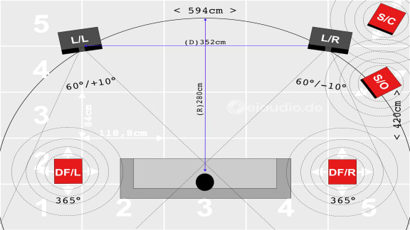
As the main door to our real-life listening room was located on the left-hand side of the front wall, our HiFi setup had to leave the entry way clear and was centred towards the right wall. Due to this small imbalance I could not help but wonder if placing the subwoofer to the right side of the left speaker (S/L) might provide better room integration, but I found that this only led to dominant bass pressure on the left. Perhaps placing our single subwoofer right in front of us might have worked better, but if you consider the radius around the listening position, you will see that this leaves no room for a rear-ported subwoofer. In my further attempts, corner placement (S/C) produced a slow, non-musical, and bass-heavy sound. Looking at the radius around the listening position, and considering the length of the diagonal crossing, this was perhaps not too surprising. The overly boomy sound in this position was surely increased by the DA Dream 2 being rear-ported.
Closed cabinet down-firing subwoofers perhaps would have offered some advantages in placement flexibility, however, I once owned a closed cabinet down-firing Canton Karat-series subwoofer that somehow sounded misplaced wherever it was. I have heard it said that two down-firing subs placed near the sitting position could work well with movies, and this might be true for systems using DSPs, but for classic 2-channel setups without DSP such delays and phase shifts should prove problematic. In the placement of our front-firing rear-ported DA sub, I finally decided that a 90° angle position behind either of the main speakers worked best. In this arrangement, the subwoofer’s position was no longer obvious. I also set the bass volume to a level that would make the sub untraceable until it was turned off, when the bass notes went sorely missing. With the 90° angle, I sadly lost the exactness I had experiences with the front-firing subwoofer. Bass nuance and layering were far less pronounced and bass punch, too, could have been better.
I spoke to friends in the industry about my findings, and they suggested that rear-ported subwoofers were difficult to place, because they had a built-in delay of the rear-projected bass bouncing off the walls. They would have preferred a front-ported design. They also pointed to the mismatch between the single 30cm woofer adding the bass lines to two 38cm midrange drivers. This match would lead to unintended differences in running time, because the subwoofer would need to compensate with a much higher amplitude. They also pointed out that running both the tops and the subwoofer through the sub’s active crossover would have resulted in a cleaner crossover point. Both friends agreed that using two subwoofers of adequate size and configuration would have been beneficial.
In summary, I can report that subwoofers are loudspeakers and should be treated as such during placement. When working with full-spectrum main speakers and the subwoofer only cuts in below 40 Hz, one might not need to worry about exact placement so much, although the system would still benefit. But when paired with speakers such as the Shure 701 Pro Master that need an extra woofer to take over from 50-60 Hz, exact placement of the subwoofer will make a noticeable difference. Good results can more easily be accomplished using two subwoofers instead of one. This is especially true, for those looking for an audiophile stereo listening experience with well-timed and proportionate musicality.
Parameters for Consideration
- room width, depth, and height
- room furnishings and wall treatment
- setup distances and radiation axis
- phase and time coherence
- subwoofer ports and vents
- low cut and crossover frequencies
- diaphragm size and mass coherence
28. Watts, Sound Pressure, Decibel

My first memories of leafing through advertisements for HiFi gear stem from mail order catalogs during the early 1980s. There were a handful of units presented on each page with small numbers linking the photos with crammed description boxes that provided a short list of specifications. Due to the fact that the concept of mail order required for purchase decisions to be made remotely, without the possibility of sensory feedback, I remember weighing my interest based on two criteria: the aesthetics of the design and the wattage output of amplifiers. In terms of design, I found myself veering towards shiny buttons, bright lights, and large power meters. When it came to watts, I was inclined to follow the simple rule of ‘the more power, the merrier’. Luckily, I did not have the means to make a purchase myself, and my parents objected to purchasing from mail order catalogues altogether.
In later years, I sometimes came across such HiFi systems at friends’ houses and was surprised to find loudspeaker cabinets that were made of resonant chipboard with smallish-looking drivers that were often surrounded by painted or glued-on silver rings to make them look more impressive. The amplifiers claiming to offer 1,000 watts of power output weighed half of my 40 watts receiver and sounded rather tame and weak-chested. Taking a look inside, there was little electronic basis behind the large power meters to back up the bold claims. But how then was it possible that the technical specifications did not translate into superior sound quality and power output? At that time, I did not have a good explanation for this phenomenon and only made a mental note that I had better be careful when purchasing gear, in order to receive real value for money and not fall for inferior quality.
Many years have passed since my early explorations, and I have since learned that a HiFi system’s ability to play music clean and loud depends on four basic factors: 1. the continuous (not peak) power output potential of the amplifier into a given Ohm load (rated in watts, RMS); 2. the maximum power handling capacity of the loudspeakers at that Ohm load; 3. the loudspeakers’ power sensitivity level (dB, at 1W/1m), and 4. the preferred listening distance from the speakers. The distance is important, because the listening volume halves as the listener’s distance to the speakers doubles. The decibel (dB) rating itself is measured at 1 watt input and one meter distance from the loudspeakers. Decibel is a logarithmic scale to measure volume that was introduced by the American Bell telephone company to measure signal loss on long runs of telephone lines.
Zero decibel was defined as being near silence for adult listeners, and ten decibel were defined as ten times this amount. With the scale being logarithmic, twenty decibel were defined as ten times louder than 10 decibel, thus resulting in 100 times the sound pressure level, and so on. Following this scale, a balloon exploding at 150 dB is one quadrillion times louder and normal conversation is one million times louder than a volume level near silence. The table called ’Sound Pressure — Sonic Event — Decibel’ provides an overview of everyday sounds, their decibel ratings, and the corresponding sound pressure levels on a linear scale from near silence to the most deafening sound. Hearing loss from high listening volumes is usually the result of a combination of being exposed to a very loud sound over a longer time period. While a popping balloon may have the potential to surprise or even frighten us, there is little risk to our ears.
The decibel scale proved to be useful for sound pressure level measurements and is also said to be much closer to the human perception of sound volume than the linear scale. However, it does not match the human ear exactly. Humans perceive the listening volume to double with every increase of six decibel. The table ‘Sound Pressure — Sonic Event — Decibel — Human Perception’ therefore aims to bring some perspective to this difference. According to the human ear, a popping ballon is approximately twenty-five times louder than near silence, not one quadrillion as the linear scale would suggest.
The table ‘Amplifier Power — Speaker Decibel Output’ contrasts the characteristics of two contemporary loudspeakers: the British Tannoy XT8f dual-concentric towers and the German Duevel Planets. The table shows that it takes ten times the amp power for the speakers to play 10 dB louder, regardless of the loudspeaker chosen. In calculating the necessary amplifier power, I factored in 3 dB headroom, which I felt to be realistic for real-life indoor applications. The Tannoy towers started from a commendable sensitivity rating of 91 dB 1W/1m. Listening from 9ft or two meters distance, one watt of power produces 79 dB. This volume level is comparable to being in a noisy restaurant and should be sufficient for most applications. At full 100 watt capacity, the Tannoys produce 99 dB of sound pressure at two meters distance (which is the equivalent of having a running motorcycle in the room) or 89 dB (similar to a person shouting) at 10 meters distance. This should be plenty of sound pressure to entertain the occasional party.
The Duevel Planets are rated at 85 dB (1W/1m) and come in at 73 decibels when listening at two meters distance. They reach the Tannoy’s comfortable 79 dB at four watts only, and, at this time, the amplifier already needs to do quite a bit of work. At their maximum 50 watts capacity, the Duevels produce 90 dB (shouting) when listening at two meters distance and 80 dB (noisy restaurant) at ten meters. This means they are less equipped to power living room parties than the Tannoys. The nine decibels in resulting difference will make the Tannoys seem 1.5 times louder than the Duevels.
As we can see for these findings, human the human perception of sound pressure is not linear. With perceived volume doubling every 6 dB, it is more similar to the logarithmic decibel scale. Amplifier watts are only meaningful when they are also quoted as continuous and not as burst or peak power. In fact, peak power output can be ten times higher than continuous output, if the capacitors are large enough. Amplifier output wattage depends on the Ohm rating on the connected speakers. An amplifier rated at 8 Ohms will produce much higher power into a 4 Ohm load. Sufficient amplifier wattage paired with high sensitivity and high power handling capacity on the side of the speakers will lead to high sound pressure levels, if so desired.

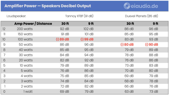
29. Room Mode Calculations

I first heard the term ‘room mode’ mentioned when a friend of mine came by our house to audition our newly acquired Martin Logan SL-3 electrostatic loudspeakers with me. Jens, who had spent some years composing music and collecting analogue modules, was not immediately taken in by the large sound canvas of the Martin Logans and instead pointed out that there was an obvious lack of bass-slam from such large speakers. He went on to suggest that this lack might be attributed to room modes and that proper alignment of the speakers and the listening position might fix it. However, as I did not understand what he was talking about, I rather believed the speakers themselves to be at fault. I wondered, if the crossovers had been tampered with, if they needed to be recapped, if perhaps the amp was too weak, or if the Mylar diaphragm had somehow lost its magnetisation. When Jens left later that night, I was therefore feeling quite shattered.
The next person to visit us was my audiophile companion Luigi. He listened to the Martin Logans, was not especially pleased with their ‘tall stage’ impression which resulted from their sheer height, and started moving them around the room with me. He suggested that greater distance to the front wall would improve imaging and stage depth, and I tentatively agreed with him. We found a position about 1.10 meters into our 5.60 meters deep room that worked well, and we both left our session in a mental state of unsettled turmoil. The Martin Logans were not so easily placed because of their dipole nature. Even one centimetre of deviation in wall distance could mess up imaging, tonality, rhythm, phase coherence and speed impression. It then took me another four weeks to determine the exact position for the SL-3 to finally lock in with our listening room.
I spent the next months upgrading the amplifier and improving the wiring. I also found a CD player that sounded more analogue and a phono cartridge with improved tonality. I sorted out grounding issues, eliminated trailing edge transformers from the proximity of the system and could hear gradual improvements with each step. Upgrading to solid-core silver cinch/RCA interconnects offered superior dynamics, and symmetrical power cords served to bring about the finishing touches. The system had become revealing and tonally rich. The sound stage was impressive, even if a little taller, as Luigi was quick to point out. The position of the speakers had been found by ear over the course of many months. I could hear that 1.12 meters distance worked well, but I did not know why this was. In fact, I was feeling uneasy about swapping speakers to run new tests for eiaudio. Luigi joked that he had some friends who were so scared to lose what they had accomplished that they set their systems up for life. That prospect did sound pretty sad.
I did not want to be that kind of audiophile. Instead, I preferred to stay true to my mission of exploration that is proposed by the title of this blog. I needed to find a solution of how to set up speakers quicker with more assurance of having found the best position. Then, one day, as I was standing at the shack of my favourite audio technician, I heard him speaking to one of his customers inside. I did not want to interrupt, but as I was listening, I noticed that his customer was speaking very soberly about some basic issues in HiFi that had also troubled me for some time. I could feel that we were kindred spirits and decided to step inside. We were quickly introduced and started speaking about the subject of cables, interference, and grounding, carefully checking each other out, because some people can be quite stubborn insisting that their current state of knowledge should be the end of everyone’s explorations. We were both relieved to find that this did not seem to be the case. At the end of our talk, I gave Peter Englisch my eiaudio.de business card and invited him to join the blog discussion. He said that he would have a look, and we went separate ways.
Some weeks later, I gave Peter a call, and he seemed happy to hear from me. As it turned out, he had read all my articles in the High Fidelity section and was somewhat pleased with the contents he found. He pointed out that, in some of the articles, although my description was accurate, it was also apparent that my grasp of the subject did not yet allow me to present the issue in a nutshell or state the single cause of an issue. I agreed that this was most likely the case, because I had not first studied the subject but instead worked my way towards a solution while moving from the practical application towards the theory. I felt proud of the progress I had made in just over two years, and he offered to help me take it a little further. Peter informed me that he had written a number of Excel sheets that allowed him to enter room dimensions to derive from them the best possible speaker positions. He offered to send me his spread sheets and promptly did so later that day. I confess that it took me a few weeks do get over the shock of seeing so many numbers and graphs on each page. With some time, however, the initial panic subsided and allowed me to work with the sheets.
I took our laser length meter and measured the inner dimensions of our main listening room to be 5.58 meters in depth, 4.78 meters in width, and 2.78 meters in height. The walls had some furnishings which would have some impact on sound, and I considered the resulting alternative measurements where the furniture affected room dimensions at ear level. Most prominently, there was one Ikea Besta cupboard that narrowed the left side wall by 0.43 meters at the listening position, resulting in 4.35 meters width. Upon entering the results of my measurements in the Excel sheet, I saw that each of the three dimensions (h, d, w) was treated separately without apparent effect on the others. The Excel sheet also did not care if the height and the width value were swapped: The results looked the identical, although one would probably notice the mistake in entry when setting up the speakers in this way. I found that a greater wall-to-wall distance always led to lower resonance frequencies, of which there were three: the first room mode, the second, and the third.
The first room mode was the strongest and the result of the speed of sound of around 340 m/s interacting with the space between the room walls. The other two were harmonic resonances that occurred at double and tripple the frequency of the first room mode. Since sound waves peaked along the room walls where they were reflected backward, the nulls were spread across the room. For the first room mode, the null was at half the room depth (at 2.79 meters in the case of our room example). I learned that sound waves were different from electrical waves, as the floor of a listening room folded the bottom half of the potential sine wave upwards, thus placing the first resonance frequency at half the calculated resonance. The resulting calculation for the room depth resonance was:
340m/s (speed of sound) ÷ 5.58m (room depth) = 60.93 Hz (sine wave)
60.93 Hz (sine wave) ÷ 2 = 30,47 Hz (1st Resonance)
The second depth resonance was at 60.93 Hz and produced three peaks in the room. Next to the natural peaks at the walls, the third peak was in the room center. The resulting two nulls were at the center of each room half, as if there was a wall between the halves where they could also accumulate. The third resonance was at 91,40 Hz and acoustically divided the room in three. The graph looked as if two separating walls were separating the three parts producing a null in each center and a peak at each imaginary wall. This created three nulls and four peaks over the total room depth.
Since resonances could accumulate or cancel each other out, the best positions for setting up speakers and for the listening position were those in which the specific room resonances produced a natural balance in the relevant frequencies. In his descriptions, Peter referred to these locations as preferential positions. And although their factors remained the same for normal rooms, the resulting value would change with the dimensions of each listening room. The factors for the calculation of the preferential positions were:
Factors: (+3) 0.125 — (+2) 0.2 — (+1) 0.45 — (-1) 0.55 — (-2) 0.8 — (-3) 0.875
Results: (+3) 0.70 m — (+2) 1.12 m — (+1) 2.51 m — (-1) 3.07 m — (-2) 4.46 m — (-3) 4.88 m
The distances provided in meters underneath each factor show the preferential positions for our room depth of 5.58 meters with all distances being relative to the front wall. The factors with negative numbers are actually mirror images of the first three factors and could more easily be measured from the back wall using the first three values. The mirror axis being at 0.5, which is half the room’s depth. I could see that the room dimensions had an effect on the first resonance frequency and the two harmonic counterparts, with larger rooms having lower resonance frequencies. The lower the frequency, the easier it was to place speakers in the room without interfering with our ear’s most critical frequencies, which are commonly around the spectrum of the human voice.
Doing the calculations for our upstairs listening room produced far lower resonances than our main listening room. The upstairs room, which also served as our office, measured 15 meters in depth and 11 meters in width. There were no parallel walls, and also the ceiling elements were of various heights. The room depth resonance frequencies were 11.3 Hz, 22.67 Hz, and 34 Hz correspondingly. The resulting preferential positions were:
Factors: (+3) 0.125 — (+2) 0.2 — (+1) 0.45 — (-1) 0.55 — (-2) 0.8 — (-3) 0.875
Results: (+3) 1.88 m — (+2) 3.0 m — (+1) 6.75 m — (-1) 8.25 m — (-2) 12 m — (-3) 13.13 m
When looking for the preferential positions for loudspeakers with respect to the width of the room, placing the speakers in mirrored positions along the room’s center axis would have produced a null in the listening position, because the latter was then located in the center of the room to form an isosceles (if not equilateral) triangle with the speakers. To avoid this effect, positions of varying wall distances had to be preferred. For our smaller 4.78 meters wide room, this could for example be a combination of factor 0.125 = 0.60 m and factor 0.2 = 0.96 m. The width distances were measured from each speaker’s center axis to the wall, whereas the depth distances was measured from the woofer’s voice coil to the front wall.
In larger listening rooms, the highest order resonances were quite frequently produced by the limited ceiling height of the room. In our 2.78 meters high room, the resonances were 61.15 Hz, 122,30 Hz and 183,45 Hz. Preferential positions were calculated to be at factor 0.125 = 35 cm and factor 0.2 = 56 cm. The vertical distances were measured from the central axis from the largest woofer to the floor of the room and had to be identical for both speakers.
The main listening position ought to form an isosceles triangle with the speakers. If the result was an equilateral triangle, this was even better. For the tonal balance, however, it was of far greater importance that the listening position corresponded with one of the preferential positions in the room. Once we began positioning the speakers and ourselves according to these factors, the first outcome was already quite acceptable. And it was from this assurance the we were able to begin with the fine tuning of the speakers to the wall materials, carpeting, and various furniture by moving the them a few centimetres or moving the listening position slightly in order to compensate for unwanted room accents. I found Peter’s method highly useful and will keep it in my toolbox for any upcoming adjustments.

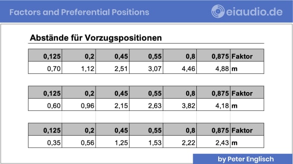
30. High-End Network Noise Filter
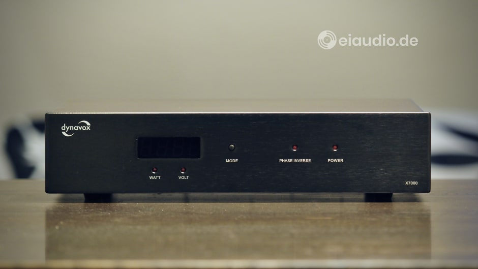
Sintron Distribution GmbH sells a whole range of affordable gear under the name of Dynavox to target entry-level audiophiles. Among the many worthwhile components, there is the VR-70E II tube amplifier that, with some minor amount of tweaking, performed very well in our listening setup. The Dynavox brand name can also be found on audio accessories such as cables, plugs, and power distributors both with and without filter technology. The Dynavox X7000, which lent its components to the construction of the High-End network filter that is the subject of discussion here, had most likely been a capable power conditioner to begin with. However, the aim of this construction project was to take filtration technology to the next level.
My first exposure to the High-End network filter project was on one of my routine visits to my trusted audio technician. As I walked into his shack, I could see him applying a string of ferrite beads to a freshly laid power cable inside the Dynavox X7000’s housing. I was surprised by the amount of free space inside the large X7000 cabinet, and Winfried explained that the original filter design had only taken up about a hand’s breadth of room inside the 43cm wide enclosure. And yet, the unit was large enough to hold far more sophisticated filters and even allowed for the use of isolating transformers. Winfried further explained that Dynavox’s use of high-quality materials on the cabinet, sockets, and switches made it the ideal basis for his new construction.
This must have been in early 2020, and it was not until two years later that I asked Winfried what had become of his High-End network filter design. He seemed pleased about my asking and offered to lend it to me for a few days so that I could find out for myself. He explained that he had galvanically separated the audio circuit from the household grid through isolating transformers allowing for 300 watts of throughput power. When seen from the rear of the unit, looking from left to right, there were two power sockets filtered for analog music sources, two power sockets intended for digital music sources, and two sockets without filters. On the power input side, a number of ferrite beads served to prevent high frequency noise from passing through the interior circuits.
Winfried’s new power filter stages were designed to target the anharmonic frequencies of 50 Hz. These were at 150 Hz, 250 Hz, 350 Hz, 450 Hz, etc. The filters became more effective the higher the anharmonic frequency was. Distortion measurements conducted by an independent laboratory found the filter strength to be 60 dB at 1,000 Hz and 90 dB at 10,000 Hz. These were very good results for any power conditioner. In addition to this, Winfried’s High-End network filter provided DC protection through a combination of bridge rectifier and capacitor and also maintained the original voltage control display that could be switched off for maximum noise protection. The touch and feel of the finished unit was great. It felt as if it had been carved out of a solid piece of metal, an effect that was supported by its weight.
Back in our upstairs listening room, I connected the filter to the same wall outlet that had already proven itself as being relatively free of distortion on our existing system. As we lived in an apartment building that was a home to four families and located in a mixed residential and industrial area, all observations on the electrical noise floor were relative and subject to change, depending on the day of the week, the time of day, and the number of other household devices that were active on the grid. In addition to this, our house was located within a five kilometre radius from the airport and about 800m beeline from the local tram and train lines. On clear days, we also had unobstructed view of the radio tower on Feldberg and the airport’s revolving radar with visual signal light—not to mention the many cellphone antennas that were perched on nearby buildings.
To filter out the cacophony of electric noises on our power grid was the proclaimed job of Winfried’s network filter. Where, if not here, could a device of this kind prove its merits? — I connected our Rotel RC-960BX preamplifier to the power output that was designed for analog devices and our Denon DCD-1420 CD player to the power output for digital devices. Both of the sources were considered solid entry-level components. I then connected my custom-built Echle LF-3519 solid state amplifier directly to the wall outlet and warmed up the system. The first thing I heard was a mild buzzing sound emanating from the filter’s large transformers, followed by the by now familiar noise floor from the high-gain amplifier. I was a little disappointed that the amplifier’s noise floor did not drop significantly with the filter attached. Sadly, this did not change even when I connected the amplifier directly to the unfiltered output of Winfried’s power conditioner.
I chose a-ha’s 2017 MTV Unplugged album “Summer Solstice” as listening sample, as it was a solid live recording with natural instruments, spoken and sung male and female vocals, and a small venue audience that could sound believable in our listening room. Songs like ‘This is our home’ provided a bass drum impression that allowed for a good sense of proportion, attack, and decay. Listening with the filter in place, I noticed that stereo imaging was much improved. ‘This is our home’ begins with a spoken introduction in which the first speaker is sitting further to the left. Without the filter, the two musicians appeared to be speaking from the same position. There also seemed to be more space around the instruments with the sound stage panning further and more seamlessly from left to right. The position of the audience seemed more realistic with fewer holes in the sound stage.
Power plug polarity had a major effect on the overall sound signature. This came as a surprise to me, as I would have expected the network filter to have a harmonising effect between the units. Without the filter in place, it was immediately clear to me which plug polarity was my preference. However, this was not so easy for me to decide with the filter in place. In one plug combination the sound became lighter and more airy and in another darker and tonally richer. I would normally have preferred the second, as it offered a stronger mid bass and a weightier and fuller sound, if it had not been for an increased amount of grain in the midrange that made vocals slightly less believable. No matter how much I tried different plug combinations, I was always left between those two choices: darker and more voluptuous with slight grain on the vocals or light and airy without the grain. But which one was correct?
Listening to music without the filter again, I noticed that tonality remained slightly shifted upward towards light, airy, and slightly sharp in the treble. Bass notes were lacking a little energy and could not free themselves so much. My preference would have been to keep the filter in place, and to set plug polarity to produce the darker tonality but without the slight sense of grain. This, however, was a result that I failed to reach on our system. I decided to report my findings back to Winfried, hoping that he could further help me in understanding the unit and the effect I had found. — Audiophiles are a tough species to satisfy, I suppose.
< 4. Power Filtering | Dynavox Tube Amp (Part II) >
Specifications
- Type: 240 volts power isolator and filter
- Isolation principle: galvanic separation
- Features: soft-start (to offset transformer magnetisation)
- Filter principles: low-frequency harmonics and HF noise
- Filter frequencies: 150 Hz / 250 Hz / 350 Hz / 450 Hz (anharmonic)
- Filter strength: 60 dB (@1,000 Hz); 90 dB (@10,000 Hz)
- DC-filtration principle: bridge rectifier and capacitor
- Throughput power (max.): 300 VA
- Power sockets (switched): 2x analog, 2x digital, 2x direct
- Switchable display (on/off): mains voltage input, LCD (amber)
- Cabinet basis: Dynavox X7000 Power Conditioner
- Dimensions: (W) 430mm x (H) 100mm x (D) 305mm
- Country of manufacture: Germany (custom-made)
- Weight: 18.5 kg
- Year(s): 2020 - 2023
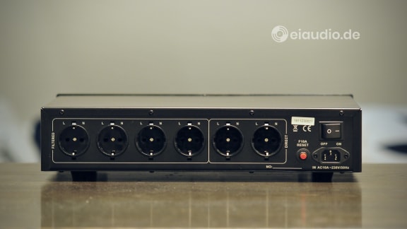
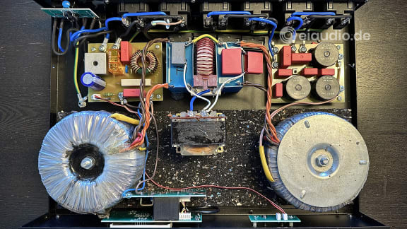
31. Understanding Room Acoustics
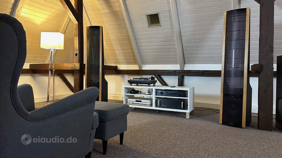
Often, even before we listen to a classical instrument, we can imagine how it sounds just from looking at it. This might seem like a bold statement, but think about it: A cello, for instance, is a large wooden instrument with long thick strings, whereas a saxophone is a brass instrument on which air is blown past a reed into a tube that culminates in a horn. Is it not true that we would imagine the cello to sound warm and wooden and the saxophone to sound cooler and more tinny? And would we not expect the larger cello to play low frequency tunes and the smaller and horned sax to play higher notes and very loud?
The sound of classical instruments is mostly determined by their size, shape, and inner dimensions, because these features serve to create rooms and chambers in which the instrument’s sound is shaped and amplified. The source of the sound (strings or reed) is mostly separate from the resonating chamber itself. In the case of the cello, its strings are made to vibrate and resonate over a well-conceived box behind. In the case of the saxophone, pressurised air passing over a reed sets it in motion, with the sound being augmented by valves and tubes and further amplified through the horn's mouth.
The exact match of the strings with the body of the cello, or of the reed with the size and design of the saxophone, finally determine how each instrument sounds. Great instruments get this balance just right, and no one would imagine that inserting a louder reed or getting more power to the strings would greatly improve the sound. And most of us would not think of changing the position of the reed or strings either. Instead, it is simply understood that the source of the sound and the corresponding chamber need to be perfectly matched for the instrument to deliver the optimal sound. In fact, it is the precise matching that gives each instrument its own distinct tonal colour and character.
When first entering the realm of High Fidelity we might be led to believe that larger loudspeakers or or more potent amplifiers will solve the issue of lacking musical presence or improve bass performance in a room. However, the instrument analogy shows that proper calculations and correct loudspeaker positioning within a room are just as important. More power, speed, and accuracy will in a first step serve to accentuate flaws in the setup, which is often the reason behind expensive High End systems sounding quite unbalanced in their owner's homes.
The more classical instruments we have heard and the more materials we have touched and played with, the better we become at predicting an instrument’s sound even before we actually listen to it. Experience, attention, and imagination play an important role when it comes to listening. Children, for instance, are often said to have superior ears, especially when it comes to detecting high frequency sounds. And that is probably true, however, the physical ear mechanics only play a very small role in respect to critical listening skills. This is how children are far more likely involved in traffic accidents than adults. Although they may hear a vehicle approaching, their cognitive skills are not yet fully developed, so that the bending of sound waves from the speed of movement and the increasing volume of an approaching vehicle will mean very little to them. The ability of the brain to filter and pay attention to specific sounds in order to derive meaning from them only evolves with listening experience.
In that same way, I must confess that room acoustics meant very little to me, until I first owned a room that I could personally build from scratch and thereby experience the steps of transformation first hand that were necessary to make it sound great. It was not until we moved to Marne, a small town at the North Sea coast of Germany, in summer 2023, that I had a dedicated listening room for experimentation. Located under the roof of the building, the wide open space was initially an attic with visible beams and bare insulation that was still dangling from the ceiling ready to fall off. I remember clapping my hands in this room and being thrilled by the fact that there was no echo to be heard. At that stage, I was standing in “silent” room, perfect for listening adventures.
Original Room Presentation Video
On the other hand, the attic was also dusty and still poorly insulated. Bugs and spiders had invaded every nook and cranny, and I could hear the wind blowing through small gaps under the shingles. This was no place to set up our Martin Logan electrostatic speakers. High voltage panels are dust magnets, and turntables to not benefit from dust and wind either. To turn this space into a studio for audio auditions would require some effort. We began work by insulating the floor and adding an extra layer of OSB (Oriented Strand Board). And we decided to preserve the original tongue and groove boards on the side walls and only added an extra layer of insulation to the ceiling, which we then covered with one layer of plaster board.
At this stage of development, clapping my hands in the room led to quite a different result: The OSB floor and the tongue and groove walls still gave off a warm and pleasant air, but they also reflected a lot of sound energy instead of absorbing it. The slightly domed ceiling gave the room an even more confined and boxy impression with an audible reverberation despite its generous height of three meters. The listening room was 7.80 x 9.20 meters in size, and so the first, second, and third order resonance frequencies were relatively low, starting at 18 Hz, however, there was plenty of time for the higher frequencies to bounce off the smooth ceiling and walls and reflect back to the listening position with obvious delay.
On the positive side, there were lots of open wooden beams to deflect some of the reverberation energy and three of the side walls were sloping from about 95cm height. The tongue and groove wood cladding also provided some natural deflection, especially of the higher frequencies. And the one straight wall in the room had a large recessed portion leading towards a narrow storage space in the back. On the negative side, the room was relatively square, which might serve to further accentuate specific room modes. And, most obviously, there still were no furnishings and fabrics in place to absorb some of the reverberation energy.
The most pressing first step, therefore, was to lay down a carpet that would cover the complete floor. Carpets are great at absorbing acoustic energy and can be used in combination with rugs to provide an even greater absorption effect. Once the carpet was in place, we brought in the first loudspeakers and set them up as described in the chapter on Room Mode Calculations. In keeping with our instrument analogy, it really does matter where the sound generator is positioned and what building materials are found in the room. After all, the listening spot is to be provided with a relatively linear sound over all frequencies that is similar to the experience of the sound engineer when listening to the recording via a decent pair of stereo headphones in the studio. For this to be the case, both the speakers and the listening position need to be in correct relation to each other and to the room.
Obviously, our journey of exploration is not finished here. The completed room with carpet still sounded far worse than the unfinished room that I originally fell in love with. Be sure to read the chapter on room mode calculations for loudspeaker positioning and the chapter on acoustic treatments to learn about some of the easy fixes to sound issues.
As always, let me know how you feel about this chapter of the journey. Reflecting on your own experiences, how have room acoustics affected your enjoyment or perception of sound? Share your stories in the comments below — I'm eager to hear about the unique soundscapes you've encountered!
< Room Mode Calculations | Acoustic Room Treatment >


32. Acoustic Room Treatment
HiFi audio systems usually find their place within a family's the living quarters. Some of them serve as entertainment centres in the living room; others form part of a home cinema setup. Audio systems may accompany an evening meal in the dining room or make working time more enjoyable in the study. Some are part of a bedroom suite or even complete a children’s room. Many households have only one large living room, which is used for everything from cooking to entertaining. In fact, very few households can afford the luxury—or have the sense or wisdom—to dedicate an entire room, or even an entire floor, to listening. And of those who do, very few homeowners have chosen or designed their homes solely for this purpose. In fact, HiFi is often the last thing on a homebuyer’s mind.
And yet, when Sabina and I toured the north of Germany in search of a home for our family, I stood for the longest time in that cathedral-like empty space under the roof of our (now) house, clapping my hands in disbelief at the unbroken silence that greeted me each time. "I want this room!" I thought. "We need this house for our family, for the language school, and certainly for the sake of my continued audio explorations. At the time, the 1980s glass wool insulation was dangling in large sheets from the ceiling beams, and the floor was a single layer of worn wooden planks with visible cracks between them.
eiaudio Moving to Marne in Summer 2023
Watch the video on YouTubeIt was clear that this magnificent-sounding room could not be left in its original, unfinished state. The lack of insulation was causing significant temperature differences between day and night, and between summer and winter. And the wind was blowing through the shingles, bringing dust and insects into the house. My challenge was to tame this wild beast without breaking its delicate spirit. To do this, I had to find out what made the original room work so well for audio purposes, and ensure I maintained and built upon that. I started reading up on room acoustics and quickly realised that there were some established listening room standards that our space met quite well.
For one thing, the room had almost no parallel walls that would have accentuated first-, second-, and third-order resonances. Instead, the side walls were almost three metres high and sloped inwards at a 45° angle from a height of about one metre to the roof. The structure itself was supported by exposed wooden beams with many uneven tongue-and-groove boards between them. One of the few straight walls along the side was made of exposed brick. The central part of the roof had a slight dome shape, rising 30 cm in the middle. There was plenty of open space to arrange the loudspeakers according to their acoustic needs, and room for me to walk behind each HiFi rack when setting things up. This meant that I could access my setups from all sides if necessary and take care not to accidentally cross signal wires.
I first consulted an acoustics expert on the best flooring for the room but felt that his preferred combination of insulation and screed would be too heavy for the old building. So, instead of pouring concrete, I added a 30 mm layer of OSB, which we covered with carpet. It was important to me to maintain the structural integrity of our building. However, this meant that I had to find a way of damping the resonance that traveled straight down from the speakers into the floor. I gave this some thought and decided that 38 kg slabs of concrete—the kind used to lay a garden path—placed directly under each speaker would act in a similar way to screed. At the same time, the slabs allowed me to place the spikes of each loudspeaker directly onto the concrete for greater structural stability. As a result, the soundstage and clarity improved dramatically, and floor resonance was reduced by around 50%.
I understood that designing a room to handle acoustics effectively requires a balance of absorption, diffusion, and (sometimes) bass trapping to manage reflections, standing waves, and reverberation times. I therefore set about determining the most linear position for each loudspeaker and the corresponding listening positions using the room mode calculation sheets provided to me by Peter English. I then set up my UMIK-1 measuring microphone with REW software to analyse the output of my speakers and the reverberation times of the room over the frequency spectrum as perceived from the listening position. It is sometimes said that covering 30% of the wall surface with absorbing materials will give a relatively natural sound impression. In rooms where typical household remedies such as bookshelves cannot be placed, professional sound absorbers from specialist shops are an option.
In general, the absorbing materials should be placed where the sound waves from the speakers are reflected directly from the walls and ceiling towards the listening position. These locations can be identified by moving a mirror—held parallel to the wall—along these surfaces until the loudspeaker drivers are visible from the listening position. In the case of our studio, I used the open joist structure of the room to hang curtains in the corners and along both sides. Rather than leaving them open, I gathered them together with a rope to form large, soft columns. This already quietened the acoustics and made conversations in the room a much more pleasant experience.
Instead of the usual windows, our listening room has small openings covered with 30 x 30 cm Perspex panels. These were less of an acoustic problem, but we did have a 120 x 60 cm window to the adjacent control room, which caused some harsh reflections. I used blinds to effectively diffuse the sound reflections from the glass. However, when I sat down to listen to the result, I could still hear that I was in a large room. I suspected that the few straight walls were reflecting too much sound, causing echoes.
As we had just bought and renovated our entire building, I needed to come up with an inexpensive solution for suitable absorbers. I found this on Michael Wynne's YouTube channel "In the Mix", where he builds 1200 x 600 x 100 mm acoustic panels using wood, damping materials, and cloth. In my case, I used jute mats (density 45-50 kg/sqm) recycled from old bean and coffee bags to dampen the treble and midrange. Shredded jute is an inexpensive choice, but there are some drawbacks: the damping factor is acceptable, but certainly not on par with more professional solutions such as Basotect (compare: rock wool 50-200 kg/sqm). There was also an unpleasant smell of mouse droppings at first. As a child, I once visited my uncle at the Bavarian public radio station and, walking past an absorber wall, had the feeling of being physically sucked into a vacuum. My DIY absorbers certainly do not produce this kind of dramatic effect.
To add more sound diffusion to the room, I bought four large, bushy plants and placed them along each of the side walls. Due to the lack of direct sunlight, these plants had to be artificial. From an acoustic point of view, it makes no difference whether a plant is organically grown or made of plastic. Artificial plants have the added advantage that they do not require a heavy pot of soil and can therefore be more easily moved to different positions to address various acoustic issues. To further reduce room reflections at the listening position, I chose large armchairs with high, absorbent backrests. These serve to increase the amount of direct rather than reflected sound reaching the ears.
Since the presence of sound waves also excites the furniture in the room, especially if the floor is made of wood, I chose HiFi racks that are capable of absorbing vibrations. In these, each HiFi unit is positioned separately on a shelf, each of which rests on spikes. The hollow steel legs are then filled with stabilising quartz sand to absorb acoustic vibrations within the structure. HiFi units containing large transformers are separated from the sensitive drive units by a separate structure to ensure correct reading of the source material without external noise. The racks are then coupled to the floor by steel spike pads on 4 mm felt pads. Felt is a chaotic structure and prevents floor vibrations from affecting the drive units.
The combination of measures works very well in the room. Both the treble and midrange sound vibrant and natural without over-emphasising any frequency. Vocals sound hauntingly real with an ever-present goosebump potential. Instruments are free from the speakers and are reproduced in their correct dimensions and timbre. There is a superior order to the music. Bass is mostly neutral to dry, with lots of layers and nuances, unless it falls uncomfortably close to the exact resonance frequency of the floor. At the time of writing, this is the only flaw that I can detect in my listening setup. As with everything in life, it is a concession to our house renovation budget. It might be worth experimenting with bass traps in the future to see if they, too, might have a positive effect on performance.
< 31. Understanding Room Acoustics | 29. Room Mode Calculations >


33. SOS High End Audio Support
Let's establish the following: Very few HiFi audio systems are set up in such a way that they can actually demonstrate their considerable performance capabilities. The more expensive the setup, the more sensitive this issue becomes.
Setting up High-End equipment is particularly challenging, as its components are capable of mercilessly exposing every flaw in the system. If you are not 100% satisfied with the sound of your High-End system, even though you have invested a lot of money and set up a special listening room for it, I am confident that I can help you quickly and effectively.
In order to set up High-End audio equipment optimally, we first need to have some listening experience ourselves. This is not about enjoying music, but about the ability to perceive the interaction of a HiFi system in the room. Every setup error has its own specific characteristics: for example, harsh voice reproduction, a blurred phantom center, missing transients, unnatural reverberation, lack of tonal width, or poor bass reproduction.
For this reason, we need a different strategy to fix each individual setup error. In our consultation, I first listen to your description of the system and analyze the challenges you are facing together with you. We then look at the five most important factors that influence the sound of your high-end system:
- the power source
- system grounding
- the setup
- all connections
- the listening room
The selection of audio components also influences the resulting system sound, but far less than one might assume. This aspect only becomes interesting once all other factors have been understood and optimized. Only then can you really hear your devices; before that, you mainly hear the weaknesses in your setup.
Component matching is usually offered by retailers and websites, while little time is spent on setting up High-End systems after purchase in-store or online. Customers then usually have to figure out for themselves how to set up their new and expensive equipment. Scrolling through YouTube tutorials mostly raises more questions than it answers.
The goal of our conversation is therefore to improve the performance of your system in a simple and cost-effective way. Afterwards, you will have a better understanding of the current state of your High-End system and be able to assess what steps are necessary to unleash its full sound. I will show you how your system handles energy and how you can transport this to your ears without loss or interference.
Let's explore together

Get in touch with me
If you happen to live within reach of 25709 Marne in northern Germany and own vintage Hi-Fi Stereo classics waiting to be explored and written about, I would be honoured to hear from you!
Your contact details
All reviews are free of charge, and your personal data will strictly be used to organise the reviewing process with you. Your gear will be returned to you within two weeks, and you are most welcome to take part in the listening process. Gear owners can choose to remain anonymous or be mentioned in the review as they wish.
Thank you for supporting the eiaudio project.
Audiophile greetings,
Karsten


Audiophile Dimensions
1. Soundstage

Soundstage refers to the spatial representation of sound in an audio recording. It encompasses the width, depth, and height of the sound image. A good soundstage creates a sense of space and allows for precise localisation of instruments and vocals.
Wide:
Refers to a soundstage that extends far beyond the boundaries of the speakers, creating a spacious and expansive listening experience.Narrow:
Describes a soundstage that is tightly focused between the speakers, lacking width and breadth.Deep:
Indicates a soundstage with significant depth, where the placement of instruments and vocals can be perceived as being in multiple layers reaching far behind the speakers.Shallow:
Opposite of deep, a shallow soundstage lacks depth dimension, giving the impression that the audio is closer to the listener and without also creating a sense of distance.Three-Dimensional:
Describes a soundstage that offers a realistic and immersive listening experience, where the placement of instruments and vocals can be perceived in three dimensions: width, height, and depth.Flat:
Refers to a soundstage that lacks depth and height, giving the impression that the audio is positioned on a single plane between the speakers.Forward:
Indicates a soundstage where the audio appears to be projected more towards the listener, creating a sense of intimacy and immediacy.Recessed:
Opposite of forward, a recessed soundstage gives the impression that the audio is positioned further away from the listener, creating a sense of distance and spaciousness.Holographic:
Describes a soundstage that exhibits exceptional imaging and precise placement of instruments and vocals, creating a lifelike and hologram-like listening experience.Focused:
Indicates a soundstage where individual instruments and vocals are well-defined and distinct, without electronic haze or unrealistic time-delay, allowing for precise localisation within the audio image.Diffuse:
Refers to a soundstage where the audio lacks precise localisation, with instruments and vocals appearing unnaturally spread out or blended together.Layered:
Describes a soundstage where instruments and vocals can be perceived as occupying different layers or planes within the audio image, adding depth and separation.Coherent:
Indicates a soundstage where the various elements of the audio image are well-integrated, resulting in a seamless and unified presentation.Congested:
Refers to a soundstage that feels crowded or dense, with a lack of separation between instruments and vocals, leading to a muddled or cluttered listening experience.Airy:
Describes a soundstage with a sense of openness and space, where the audio seems to breathe and have room to expand.Intimate:
Indicates a soundstage that creates a close and personal listening experience, with instruments and vocals appearing to be in close proximity to the listener. Often, this is also associated with a warm midrange sound.Vast:
Refers to a soundstage that is incredibly large and expansive, giving the impression of a sheer endless sonic landscape.Balanced:
Indicates a soundstage where the placement and distribution of instruments and vocals feel evenly spread and well-balanced, creating a sense of harmony and coherence.Engaging:
Describes a soundstage that captivates and draws the listener into the music, creating an engaging and immersive listening experience.
2. Imaging

Imaging describes the ability of a specific HiFi stereo system or a headphone setup to accurately localise individual sounds within the soundstage. Good imaging provides a clear and precise placement of instruments and vocals. For audiophile listeners, it is often a phenomenon that fellow human beings can readily tell when a visual image is warped, distroted, cluttered, or hazy, yet are completely oblivious to the same characteristics in sound. The following expressions are used to describe imaging:
Pinpoint
Describes the ability of an audio system to precisely locate and position individual sound sources in the stereo field.Layering
Refers to the ability of an audio system to present different instruments or voices at different depths within the soundstage, creating a sense of depth and dimension.Sonic separation
Describes the degree to which individual sound elements are distinct and well-defined within the audio presentation, allowing for easy differentiation and identification.Micro-detail
Describes the ability of an audio system to reveal subtle nuances and intricacies within the music, allowing for a greater level of insight and engagement.Precision
Refers to the accuracy and precision with which sound sources are positioned within the stereo image, resulting in a highly defined and realistic soundstage.Instrument separation
Describes the degree to which different instruments are presented as distinct entities within the soundstage, allowing for easy identification and tracking of individual instrument lines.Ambience retrieval
Refers to the ability of an audio system to accurately reproduce the acoustic space and ambiance of a recording, providing a sense of the original recording environment.The expressions used to describe Soundstage and Imaging can overlap to some extent. Refer to my discussion of Soundstage for further vocabualry to describe music presentation.

