Characteristic Cable Impedance
27/01/2023
Author: Karsten Hein
Category: Gear & Review
Tag(s): Speaker Cables
The first time I heard the term ‘characteristic cable impedance’ was on one of my routine visits to Winfried Echle. The seasoned technician and developer of audio equipment explained that unmatched impedances could lead to undesired reflections that would negatively affect amplifier performance and signal integrity which could in turn also affect tonality. Later that day, I went home to check the nominal impedance of speaker cables and found this to be substantially lower than nominal speaker impedance. Realising that I was probably not looking for the correct specifications, I figured that there must be a difference between nominal impedance and characteristic impedance.
As I wanted to find out more about the phenomenon, Winfried referred me to Roland Kuhn, who had done some research on characteristic speaker cable impedance and had also constructed some cables for use with specific audio equipment. Roland sat down with me and pulled out some publications on the matter. He asked me if I had perhaps already read some of them. I told him that I had not, and that he would need to start his explanations from scratch. Roland explained that the adjustment of the characteristic impedance originally played a role in telecommunications, where signals have to be transmitted loss-free (without reflections) over long distances. However, this principle also applies to the system of amplifier, cables and loudspeakers, and mismatches would be particularly noticeable in this area, if the quality of the individual components, the correct positioning of the loudspeakers and the individual listening experience permitted.
Roland explained that the characteristic impedance of cables changed with the frequency of the electrical signal flowing through them. In case of a mismatch between characteristic impedance and the attached load (or loudspeaker), reflections occurred at the point of transition. The amplitude and polarity of the reflected wave depended on the degree of the mismatch. Graphs from the research papers that Roland showed me illustrated this effect by means of overlapping lines or ripples. From these observations it followed that the characteristic impedance of a loudspeaker cable should match the impedance of the loudspeaker as closely as possible in the range of audio frequencies.
I learnt that the differences in characteristic impedance of non-matched cables could vary by a factor of 5-20. For low frequencies, the characteristic impedance was very high and dropped asymptotically to a lower value. I could see that frequencies above 500,000 Hz usually saw characteristic impedances that were constant. It was also shown that the reflected waves that resulted from the transition to the loudspeaker would run back to the amplifier at the output stage where they could negatively affect amplifier performance, signal integrity, and, ultimately, tonality and imaging.
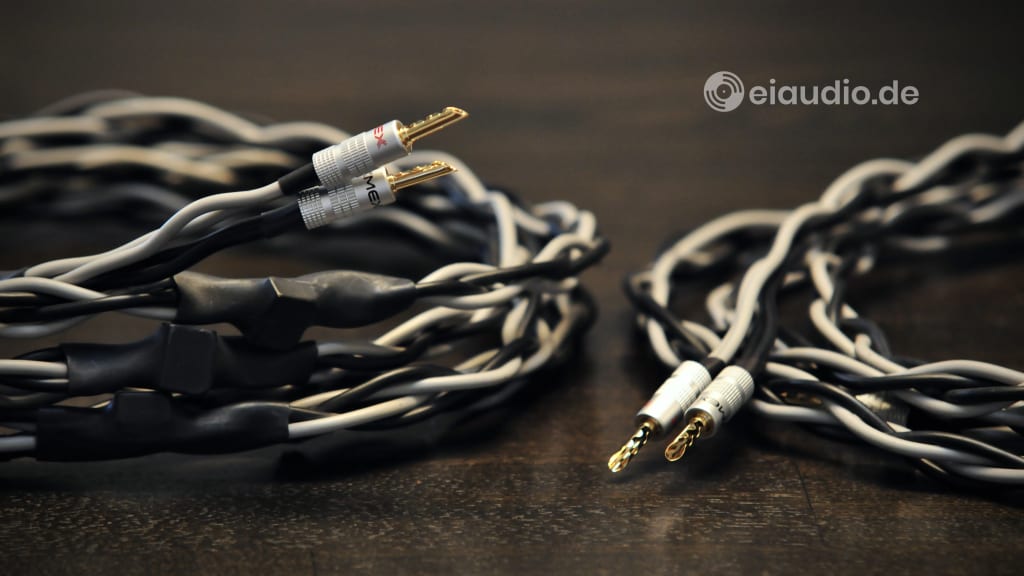
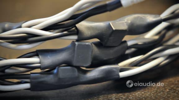
The cable that is shown here used a selection of capacitors and resistors to peg characteristic impedance roughly at the 8 Ohm value of the loudspeaker. In setting up my equipment for the listening test, I was warned that not all amplifiers were able to handle this type of cable design, and that there was an actual risk of the amplifier overheating to the point of destruction. As a precaution, I was asked to stay with the amplifier for a few minutes after turning it on to make sure that it did not react in this way.
[Review in progress. Coming up next.]
Specifications
- Type: linear wave resistance
- Material: multi-strand copper
- Resistance: 8 Ohms continuous
- Cable design: double-braided
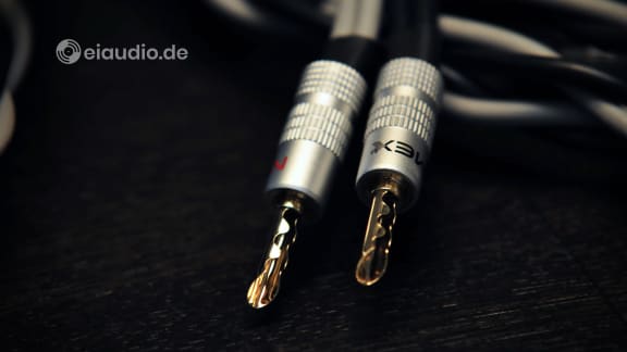
- Termination: banana plugs
- Plug-type: Nexmex 8-16 AWG, 24K gold
- Lengths: 2 meters (x2)
- Weight: 672 gr (mono)
- Country of manufacture: Germany
- Year(s): 2010


